Pick your language and provide your email: we'll send you a specifically translated version.
This manual is not available in your language
User questions about HDMI20-OPTC-TX220-FOX Lightware
0 question about this device. Answer the ones you know or ask your own.
Ask a new question about this device
No questions yet. Be the first to ask one.
Download the instructions for your Audio/video extender in PDF format for free! Find your manual HDMI20-OPTC-TX220-FOX -
Lightware and take your electronic device back in hand. On this page are published all the documents necessary for the use of your device. HDMI20-OPTC-TX220-FOX by Lightware.
USER MANUAL HDMI20-OPTC-TX220-FOX Lightware
natural_image
Two black electronic equipment units with ventilation grilles and control knobs, no visible text or symbols on the surfaces.
HDMI20-OPTC-TX220-Pro
HDMI20-OPTC-RX220-Pro
Multimode Single Fiber Optical Extender
HDMI20-OPTC series - User's Manual 2
Important Safety Instructions
Class I apparatus construction
This equipment must be used with a mains power system with a protective earth connection. The third (earth) pin is a safety feature, do not bypass or disable it. The equipment should be operated only from the power source indicated on the product.
To disconnect the equipment safely from power, remove the power cord from the rear of the equipment, or from the power source. The MAINS plug is used as the disconnect device, the disconnect device shall remain readily operable.
There are no user-serviceable parts inside of the unit. Removal of the cover will expose dangerous voltages. To avoid personal injury, do not remove the cover. Do not operate the unit without the cover installed.
The appliance must be safely connected to multimedia systems. Follow instructions described in this manual.
CAUTION AVS
RISK OF ELECTRIC SHOCK
DO NOT OPEN
RISQUE DE CHOC ELECTRIQUE
NE PAS OUVRIR
Ventilation
For the correct ventilation and to avoid overheating ensure enough free space around the appliance. Do not cover the appliance, let the ventilation holes free and never block or bypass the ventilators (if any).
WARNING
To prevent injury, the apparatus is recommended to securely attach to the floor/wall or mount in accordance with the installation instructions. The apparatus shall not be exposed to dripping or splashing and that no objects filled with liquids, such as vases, shall be placed on the apparatus. No naked flame sources, such as lighted candles, should be placed on the apparatus.
Waste Electrical & Electronic Equipment WEEE
This marking shown on the product or its literature, indicates that it should not be disposed with other household wastes at the end of its working life. To prevent possible harm to the environment or human health from uncontrolled waste disposal, please separate this from other types of wastes and recycle it responsibly to promote the sustainable reuse of material resources. Household users should contact either the retailer where they purchased this product, or their local government office, for details of where and how they can take this item for environmentally safe recycling. Business users should contact their supplier and check the terms and conditions of the purchase contract. This product should not be mixed with other commercial wastes for disposal.
Caution: Laser product
Common Safety Symbols
Symbol Description
~
Alternating current
Protective conductor terminal
Caution, possibility of eletric shock
Caution
Laser radiation
HDMI20-OPTC series - User's Manual 3
Symbol Legend
The following symbols and markings are used in the document:
WARNING! Safety-related information which is highly recommended to read and keep in every case!
ATTENTION! Useful information to perform a successful procedure; it is recommended to read.
INFO: A notice which contains additional information. Procedure can be successful without reading it.
DEFINITION: The short description of a feature or a function.
TIPS AND TRICKS: Ideas which you may have not known yet but can be useful.
Navigation Buttons
Go back to the previous page. If you clicked on a link previously, you can go back to the source page by clicking the button.
Navigate to the Table of Contents.
Step back one page.
Step forward to the next page.
Document Information
All presented functions refer to the indicated products. The descriptions have been made during testing these functions in accordance with the indicated Hardware/Firmware/Software environment:
SOFTWARE CONTROL – LIGHTWARE DEVICE CONTROLLER ...24
5.1. INSTALL AND UPGRADE 24
5.2. ESTABLISHING THE CONNECTION....24
5.3. CROSSPOINT MENU - HDMI20-OPTC-TX220-PRO....25
5.4. PORT PROPERTIES WINDOW 26
5.4.1.HDMI Input Port -Transmitter 26
5.4.2.HDMI Output Port - Transmitter 26
5.4.3. Optical Input Port - Receiver 27
5.4.4. HDMI Output Port - Receiver 27
5.5. EDID MENU....28
5.5.1. Sources and Destinations 28
5.5.2. EDID Operations.... 28
5.5.3. EDID Summary Window 29
5.5.4. Editing an EDID 29
5.5.5. Creating an EDID 30
5.6. CONTROL MENU 30
5.6.1. RS-232 Tab 30
5.6.2. Ethernet Tab 31
5.7. EVENT MANAGER....31
5.7.1. The Event Editor 32
5.7.2. Create or Modify an Event 32
5.7.3. Special Tools and Accessories.... 34
5.7.4. Clear One or More Event(s) 34
5.7.5. Export and Import Events 34
5.8. SETTINGS MENU....35
5.8.1. Status Tab 35
5.8.2. Network Tab 35
5.8.3. Front Panel Tab 35
5.8.4. Backup Tab (Configuration Cloning) 36
5.8.5. System 37
5.9. ADVANCED VIEW WINDOW 37
LW3 PROGRAMMERS' REFERENCE 38
6.1. OVERVIEW 38
6.1.1. Elements of the Tree Structure 38
6.1.2. Escaping....40
6.1.3. Error Messages....40
6.1.4. Prefix Summary 40
6.2. THE TREE STRUCTURE....40
6.3. LW3 COMMANDS 41
6.3.1. Get Command 41
6.3.2. Set Command 42
6.3.3. Invocation 42
6.3.4. Manual 43
6.3.5. Signature 43
6.3.6. Subscription 43
6.3.7. Notifications about the Changes of the Properties 44
6.4. FORMAL DEFINITIONS....44
6.5. SYSTEM COMMANDS....45
6.5.1. Querying the Product Name 45
6.5.2. Setting the Device Label 45
6.5.3. Querying the Serial Number 45
6.5.4. Querying the Firmware Version 45
6.5.5. Resetting the Extender 45
6.5.6. Restoring the Factory Default Settings 45
6.5.7. Locking Front Panel 45
6.5.8. Enabling Dark Mode 45
6.5.9. Setting the Dark Mode Delay 46
6.5.10. Setting the Dark Mode on the Remote Device 46
6.5.11. Setting the Rotary Direction of the Jog Dial Knob....46
6.6. VIDEO PORT AND CROSSPOINT SETTINGS....46
6.6.1. Querving the Crosspoint Setting 46
6.6.2. Switching Video Input 46
6.6.3. Querying the Status of Source Ports 47
6.6.4. Querying the Status of Destination Ports 48
6.6.5. Muting Input Port 48
6.6.6. Unmuting Input Port 48
6.6.7. Locking Input Port 48
6.6.8 Unlocking Input Port 48
6.6.9. Querying the Video Autoselect Settings 48
6.6.10. Changing the Autoselect Mode 49
6.6.11 HDCP Setting 49
6.6.12 Setting the Output Conversion Mode 49
6.6.13. Setting the Output Conversion Mode of the Remote Device....49
HDMI20-OPTC series - User's Manual 5
6.7. NETWORK CONFIGURATION....50
6.7.1. Querying the IP Address....50
6.7.2. Changing the IP Address (Static)....50
6.7.2. Changing the IP Address (Static) 50
6.7.3. Querving the Subnet Mask 50
6.7.4. Changing the Subnet Mask (Static) 50
6.7.5. Querying the Gateway Address 50
6.7.6. Changing the Gateway Address (Static) 50
6.7.7. Querying the DHCP State....50
6.7.8. Changing the DHCP State....50
6.7.8. Changing the DHCP State 50
6.7.9. Enabling Ethernet Port 50
6.8. RS-232 PORT CONFIGURATION....51
6.8.1. Querying the RS-232 Opearation Mode 51
6.8.2. Setting the RS-232 Opearation Mode....51
6.8.3. Setting the BAUD Rate....51
6.8.4. Setting the Database....51
6.8.4. Setting the Datablt 51
6.8.5. Setting the Stopbits 51
6.8.6. Setting the Stopbits 51
6.8.6. Setting the Parity 51
6.8.7. Enabling Command Injection Mode 52
6.9. SENDING MESSAGE VIA THE COMMUNICATION PORTS ....52
6.9.1. Sending Message via an RS-232 Port 52
6.9.2. Sending Message via TCP Port 52
6.9.3. Sending Message via UDR Port 53
6.10. EDID MANAGEMENT....54
6.10.1. Querying the Emulated EDIDs....54
6.10.2. Querying the Validity of a Dynamic EDID 54
6.10.3. Querying the Preferred Resolution of an User EDID....54
6.10.4. Emviating on EDID to an Input Port....54
6.10.4. Emulating an EDID to an input Port.... 54
6.10.5. Conving an EDID to User Memory.... 54
6.10.6. Copying an EDID to User Memory 54
6.10.6. Deleting an EDID from User Memory 54
6.10.7. Resetting the Emulated EDIDs....54
6.11. LW3 COMMANDS - QUICK SUMMARY....55
FIRMWARE UPGRADE....57
7.1. ABOUT THE FIRMWARE PACKAGE (LFP FILE)....57
7.2. SHORT INSTRUCTIONS....57
7.3. INSTALL AND UDEPADE....57
7.3. INSTALL AND UPGRADE ....57
7.4. DETAILED INSTRUCTIONS....58
7.4.1. Establish the Connection 58
7.4.2. Start the LDU and Follow the Instructions 58
7.5. KEEPING THE CONFIGURATION SETTINGS 61
TROUBLESHOOTING....62
TECHNOLOGIES....64
9.1. EDID MANAGEMENT....64
9.1.1. Understanding the EDID 64
9.1.2. Advanced EDID Management....64
9.2. HDCP MANAGEMENT....65
9.2.1. Protected and Unprotected Content 65
8.2.2. Displeable Unnecessary Epoxylation 65
9.2.2. Disable Unnecessary Encryption....65
9.3. PIXEL ACCURATE RECLOCKING....66
9.4.SERIAL MANAGEMENT 67
9.4.1.General Information 67
9.4.2. Types of Serial Cables....67
9.4.3. RS-232 Signal Transmission over Lightware Extender Devices .. 67
Thank You for choosing Lightware's HDMI20-OPTC series device. In the first chapter we would like to introduce the device highlighting the most important features in the below listed sections:
DESCRIPTION
▶ MODEL DENOMINATION
Box CONTENTS
COMPATIBLE DEVICES
FEATURES OF THE DEVICE
TYPICAL APPLICATION
1.1. Description
Thank You for choosing Lightware HDMI20-OPTC series products.
The HDMI20-OPTC-TX220-Pro and HDMI20-OPTC-TX220-Pro is a HDMI 2.0 compatible extender pair for video, RS-232 and Gigabit Ethernet signals, supporting uncompressed 4K UHD resolution at 60Hz 4.4.4. This extender pair is particularly recommended for rental and staging applications, 4K live events, and for future-proof operation centers. The extender can transmit HDMI 2.0 signals with 18Gbps over one multimode fiber to a distance of up to 700 meters.
Using the factory, custom or transparent EDID emulation the user can fix and lock EDID data on the HDMI connector. Advanced EDID Management forces the required resolution from any video source and fixes the output format conforming to the system requirements. The unit offers bi-directional and transparent RS-232 transmission and two separate Gigabit Ethernet signals over the fiber connection.
All devices can be mounted on a rack shelf or used standalone, rack ears also serve easy handling and bump protection, mounting threads on top and one of the sides to conform strict installation safety regulations.
1.2. Model Denomination
HDMI20-OPTC-TX220-Pro
HDMI 2.0 capable Transmitter unit
HDMI20-OPTC-TX220-Pro
Lightware optical standard
HDMI20-OPTC-RX220-Pro
HDMI 2.0 capable Receiver unit
HDMI20-OPTC-RX220-Pro
Model number
Lightware optical standard
1.3. Box Contents
Transmitter/receiver unit
IEC power connector
Quick Start Guide
1.4. Compatible Devices
HDMI20-OPTC series devices are compatible with each other. For more information, please check the compatibility table on www.lightware.com.
1.5. Features of the Device
4K Video without Compression
Supporting uncompressed 4K UHD resolution at 60Hz 4:4:4 colorspace.
Signal Transmission up to 700m
Video, audio, Ethernet, RS-232 signal over fiber.
18 Gbit/sec Bandwidth
The extender can transmit HDMI 2.0 signals with 18Gbps.
Conversion to 4:2:0
The receiver is able to subsample the video stream in YCbCr colorspace from 4:4:4 to 4:2:0.
HDMI 2.0 to 2x HDMI 1.4 Splitting
The device supports left and right column processing of an HDMI 2.0 4K@60Hz 4:4:4 input signal, allowing for the transmission of an 18 Gbps HDMI 2.0 signal over two HDMI 1.4 compliant links. The two halves can then be recombined at the signal destination.
Introduction HDMI20-OPTC series - User's Manual 7
Local Output
User can attach a local monitor to observe the video signal sent through the fiber optical cable. The resolution and clock frequency are the same on HDMI and fiber optical connectors, no internal scaling or conversion is applied.
Graphic Display and Rotary Jog Dial Control Knob
Easy setting and menu navigation are assured by the color graphic display and the comfortable jog dial control.
Event Manager
The Event Manager tool takes care of all the necessary control in a smaller configuration by performing predefined actions in response to device status changes. Hence, in a less complex environment, there is no need to invest in additional control solutions, which makes the receiver the best choice for numerous applications.
Dark Mode
Rental application requires this function, which keeps the LEDs until to hide the device during the event.
Mounting Threads
Mounting threads on top and one of the sides to conform strict installation safety regulations.
1.6. Typical Application
Rental and staging
Long distance lossless HDMI or DVI signal transmission
• Professional AV systems, conference rooms
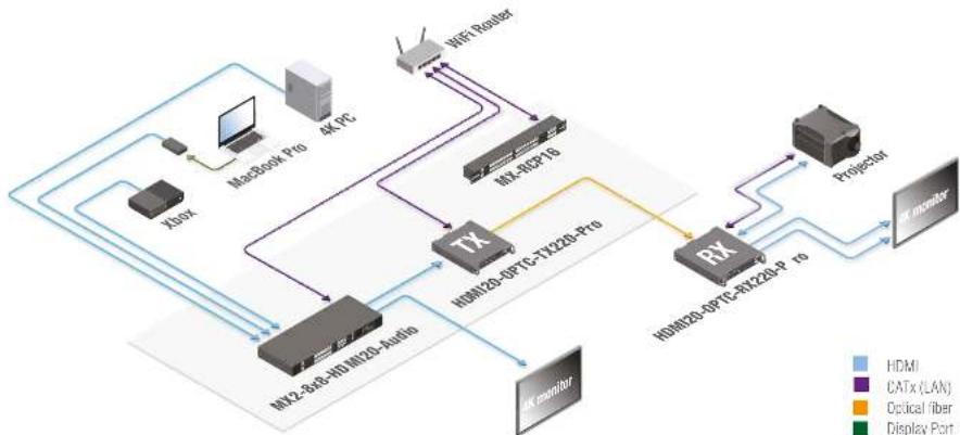
1.6.1. Integrated System Application
flowchart
graph TD
    A["MacBook Pro"] --> B["4K PC"]
    B --> C["MX-802P19"]
    C --> D["MX120-PTC-TX220-P19"]
    D --> E["RX"]
    E --> F["HDMI20-PTC-RX120-P19"]
    F --> G["RTProjector"]
    G --> H["Monitor"]
    I["Xbox"] --> J["4K monitor"]
    K["Wi-Fi Router"] --> L["4K monitor"]
    M["4K monitor"] --> N["4K monitor"]
    O["4K monitor"] --> P["4K monitor"]
    Q["4K monitor"] --> R["4K monitor"]
    S["4K monitor"] --> T["4K monitor"]
    U["4K monitor"] --> V["4K monitor"]
    W["4K monitor"] --> X["4K monitor"]
    Y["4K monitor"] --> Z["4K monitor"]
    style A fill:#f9f,stroke:#333
    style B fill:#ccf,stroke:#333
    style C fill:#cfc,stroke:#333
    style D fill:#fcc,stroke:#333
    style E fill:#cff,stroke:#333
    style F fill:#ffc,stroke:#333
    style G fill:#fcc,stroke:#333
    style H fill:#ffc,stroke:#333
    style I fill:#f9f,stroke:#333
    style J fill:#ccf,stroke:#333
    style K fill:#cfc,stroke:#333
    style L fill:#fcc,stroke:#333
    style M fill:#ffc,stroke:#333
    style N fill:#fcc,stroke:#333
    style O fill:#ffc,stroke:#333
    style P fill:#fcc,stroke:#333
    style Q fill:#f9f,stroke:#333
    style R fill:#ccf,stroke:#333
    style S fill:#fcc,stroke:#333
    style T fill:#ffc,stroke:#333
Introduction HDMI20-OPTC series - User's Manual 8
1.6.2. Standalone Application
Typical Application Description
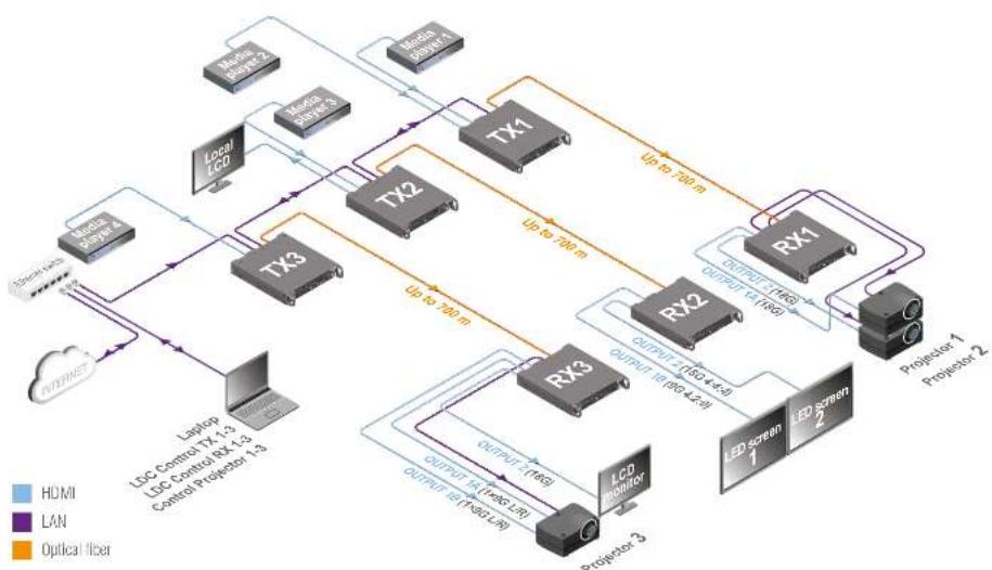
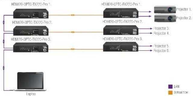
The two Ethernet connectors on each extender make possible to daisy chain the devices and build a local network where all the transmitters (1..3) and receivers (1..3) are available via LAN.
They can be controlled by Lightware Device Controller (LDC) software from the laptop. Optical fiber cable transmits the HDMI, embedded audio, Ethernet, and RS-232 signal to the receivers, so in this case, the sinks can be controlled by Ethernet commands from the control device (laptop).
In this example, all the sources send HDMI 2.0 4K@50Hz 4:4:4 A/V signal to the transmitters which extend the stream to the receivers via multimode fiber cable.
Receiver 1..3 represent three applications of the output modes:
RX1 is in transparent mode (no conversion mode), the sinks are stacked projectors. The video signal is HDMI 2.0 4K@60Hz 4:4:4 on the Output 1A and the Output 2 ports.
RX2 is in downsample convert mode (convert to YCbCr 4:2:0). The LED screen 2 is 4K compatible and connected to the Output 2 port. LED screen 1 is not HDMI 2.0 4K@60Hz 4:4:4 compliant, so the video processor in the receiver converts the HDMI signal from 4:4:4 to 4:2:0, and this way the sink will be able to accept the signal on the Output 1B.
RX3 is in split mode. The receiver supports vertical splitting of the HDMI 2.0 4K@60Hz 4:4:4 input signal to left and right halves allowing for the transmission of a 18Gbps HDMI 2.0 signal over two HDMI1.4 compliant links. The sink is a projector which is able to recombine two half signals. Video signal is transmitted to the Output 2 without any changing.
The chapter is about the installation of the device and connecting to other appliances, presenting also the mounting options and further assembly steps:
MOUNTING OPTIONS
CONNECTING STEPS
2.1. Mounting Options
Extenders can be mounted in several ways, depending on the application. They can be mounted on a rack shelf or used standalone. Rack ears also serve easy handling and bump protection, mounting threads on top and one of the sides to conform strict installation safety regulations.
ATTENTION! To ensure the correct ventilation and avoid overheating let enough free space in front of the appliance and keep the ventilation holes free.
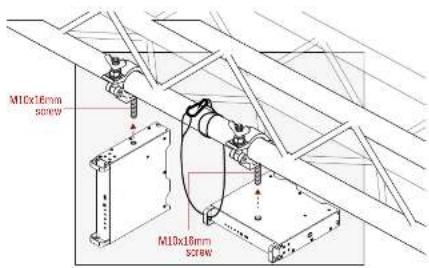
2.1.1. Truss Mounting - HDMI20-OPTC-RX220-Pro
Mounting thread on top and on one of the sides for safe and secure installation. Rigging the handles with a safety wire rope is highly recommended for safety reasons.
text_image
M10x16mm
screw
M10x18mm
screw
To order mounting accessories please contact sales@lightware.com. (Truss clamp and safety wire rope are not available at sales.)
2.1.2. Standard Rack Installation
Rack mounting kit includes all necessary accessories for Standard Rack Installation:
• 2 pcs. rack ears,
- 12 pcs. black, M4x8mm hexagon socket countersunk head screws.
Rack mounting kit is not supplied with the product, it can be purchased separately, please contact sales@lightware.com.
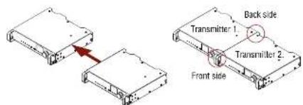
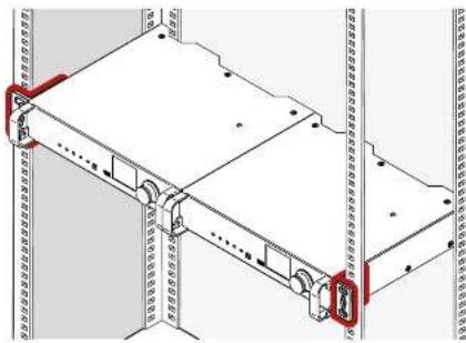
Step 1. Take two devices directly each other.
text_image
Back side
Transmitter 1.
Transmitter 2.
Front side
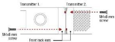
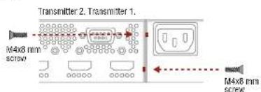
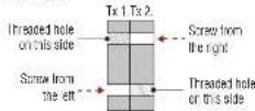
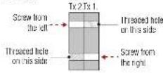
Step 2. Two mounting holes on the front ears and two on the back of the chassis is for fastening the two units to each other with 2x 2 pcs. M4x8 mm screws. This way you get a one-rack wide and 1U high device.
Front side
text_image
Transmitter 1.
M4x8 mm
screw
Front rack ears
Transmitter 2.
M4x8 mm
screw
Back side
text_image
Transmitter 2. Transmitter 1.
M4x8 mm
screw
M4x8 mm
screw
ATTENTION! Take care of the mounting direction of the screws!
Front side
Back side
Mounting direction of the screws
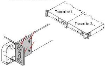
Step 3. Take the rack ears on the left and right side of the extender pair as shown in the picture. Insert the screws into the holes and fix the front ears to the devices.
text_image
Transmitter 1
Transmitter 2
Assembly of the mounting ears
Step 4. As a final step, mount the unit in the rack.
natural_image
Technical diagram of a mechanical assembly with red annotations highlighting components (no readable text or symbols)
Standard rack installation
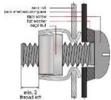
ATTENTION! Always use all the four screws for fixing the rack ears to the rack rail. Choose properly sized screws for mounting. Keep minimum two thread left after the nut screw.
text_image
max. no
max. screw
max. screw
for washer
cage out
min. 2
thread left
Mounting the rack ears to the rack rail
2.1.3. Rack Shelf Mounting (with 1U high Rack Shelf)
1U high rack shelf provides mounting holes for fastening two 1/2-rack or four 1/4-rack size units. Supplied accessories:
• 10 pcs. PZ flat head screw (M3x6mm).
Rack shelf is not supplied with the product, it can be purchased separately, please contact sales@lightware.com.
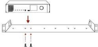
Step 1. Tum the unit upside down.
Step 2. Put the rack shelf upside down on the unit, and position it to get the mounting holes aligned.
Step 3. Fasten the unit on the rack shelf with the provided screws.
Step 4. Mount the rack shelf in the rack.
text_image
Diagram showing a device with an attached control panel and two connected ports, one with a downward arrow indicating direction.
INFO: The extender is half-rack sized.
2.2. Connecting Steps
flowchart
graph TD
    A["Video processor"] -->|HDMI| B["HDMI20 OPTC TX220 Pro"]
    C["Media server"] --> B
    D["Confidence monitor"] --> B
    E["4K projector"] --> F["HDMI2G-OPTC-RX220-Pro"]
    G["LCD screen"] --> F
    B <-->|OPT| F
    B <-->|LAN USB| H["Laptop"]
    B <-->|LAN P| I["Button panel"]
    H --> J["LW or third-party filter device"]
    I --> K["Power"]
    I --> L["Opt"]
    F --> M["RS-232"]
    F --> N["LAN"]
    F --> O["OPTRc"]
    F --> P["Power"]
    F --> Q["Lightware or third-party filter device"]
OPT
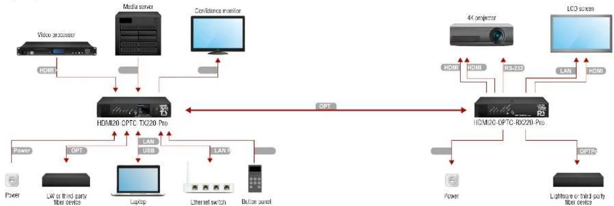
Connect a multimode (MM) fiber cable to the channel A of the transmitter.
OPT
Optionally connect a compatible Lightware device or a third-party device to the break-out LC connector. It is internally linked to the channel B of the Neutrik connector.
HDMI
Connect an HDMI source (e.g. video processor or media server) to any of the inputs of the transmitter.
HDMI
Optionally connect an HDMI sink (e.g. confidence monitor) to the HDMI output of the transmitter. The displayed signal of the output port is equal to the extended video signal.
LAN
Optionally connect Ethernet devices (e.g. switch, laptop, computer etc.) to the available Neutrik etherCON connector(s) of the extender(s). All connected devices will work as if they are connected to the same network. Ethernet connectors are not Power over Ethernet (PoE) compatible.
USB
Optionally connect a USB mini-B type cable between the transmitter unit and the computer in order to control the device (in this case only the transmitter).
RS-232
Optionally for RS-232 extension: connect a controller unit (e.g. button panel) to the RS-232 port of the transmitter with a null modem serial cable.
Power
Connect the power cord to the AC power socket to the transmitter unit. It is recommended to power on the devices as the final step.
OPT
Connect a multimode (MM) fiber cable to the channel B of the receiver.
OPT
Optionally connect a compatible Lightware device or a third-party device to the break-out LC connector. It is internally linked to the channel A of Neutrik connector.
HDMI
Connect an HDMI sink (e.g. 4K projector) to the HDMI 1A and the 1B output ports and the other sink (e.g. LCD screen) to the HDMI 2 output port.
LAN
In order to control, optionally connect Ethernet devices (e.g. 4K LCD screen) to the available Neutrik etherCON connector of the extender.
RS-232
Optionally for RS-232 extension: connect a controlled device (e.g. projector) to RS-232 port of the receiver with a serial cable.
Power
Connect the power cord to AC power socket to the receiver unit. It is recommended to power on the devices as the final step.
ATTENTION! Connecting the transmitter and receiver to the same LAN beside they are connected to each other via fiber is not recommended. In case of Ethernet loop, the extenders are not available via LAN.
ATTENTION! Always use high-quality HDMI cable for connecting the sources with the transmitters, and sinks with the receivers.
3
Product Overview
The following sections are about the physical structure of the device, input/output ports, and connectors:
FRONT VIEW
▶ ELECTRICAL CONNECTIONS
▶ MULTIMODE SINGLE FIBER EXTENDER CONCEPT
▶ OPTICAL INTERFACE
VIDEO AND AUDIO INTERFACE
▶ CONTROL FEATURES
text_image
Power Link
Power Link
NO2
High-Select
Current Connection
Function
USB
HDMI20 OPTC-2008-PI3
HDMI20 Schematic High-Select
1
6
3
LSTM
HDMI20 OPTC-2008-PI3
HDMI20 Schematic High-Select
HDMI20 OPTC-2008-PI3
HDMI20 Schematic High-Select
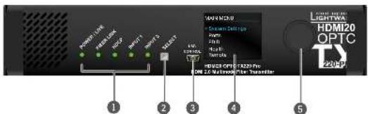
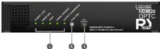
① Status LEDs The LEDs give feedback about the state, connections and certain settings of the unit. For details, see Status LEDs - Transmitter and Status LEDs - Receiver section.
2 Select button Transmitter: Select button toggles between the Input 1 and Input 2.
6 Function button Receiver: Function button sets the output conversion mode. See the details in Output Conversion Modes section.
USB Port USB mini-B port for local controlling the unit by Lightware Device Controller software.
4 LCD display Transmitter: Display of the front panel menu.
5 Jog dial knob Transmitter: Browse the menu by turning the knob, click on the desired item to check or change it.
Product Overview HDMI20-OPTC series - User's Manual 13
3.2. Rear View
HDMI20-OPTC-TX220-Pro
text_image
C-TX220-Pro
1
2
3
4
5
6
7
8
HDMI20-OPTC-RX220-Pro
text_image
1
2
3
4
5
6
7
8
9
10
CE
S
S
S
S
S
S
S
S
S
S
S
S
S
S
S
S
S
S
S
S
S
S
S
S
S
S
S
S
S
S
S
S
S
S
S
S
S
S
S
S
S
S
S
S
S
S
S
S
S
S
11
12
13
14
15
16
17
18
19
20
21
22
23
24
25
26
27
28
29
30
31
32
33
34
35
36
37
38
39
40
41
42
43
44
45
46
47
48
49
50
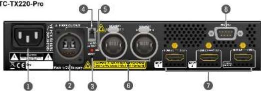
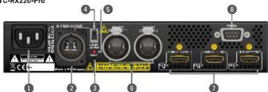
1 AC connector Standard IEC connector accepting 100-240 V, 50 or 60 Hz.
2 Fiber Neutrik opticalCON DUO LC connector for optical data transmission. The channel A connector carries the signal from the transmitter to channel B in the receiver.
3 Boot button Hidden button for special bootload function.
4 Break-out connector The break-out LC connector is internally connected to the channel B of Neutrik connector in the transmitter and the channel A in the receiver. It is to carry any optical signal from the break-out LC connector.
5 Laser LED It gives feedback about the operation of the optical module. When the laser is active (Laser LED is ON), it radiates invisible waves from the optical connector. Avoid eye exposure to beam!
B LAN Two Neutrik etherCON connectors for Gigabit Ethernet (to control the unit or for pass-through). Both are in the same local network. Remote powering (PoE) is not possible.
7 HDMI Transmitter: Two HDMI 2.0 input ports and one HDMI 2.0 output port for local display. connector Receiver: Three HDMI video output ports.
8 Serial port D-SUB connector for bidirectional RS-232 communication (control/command injection/pass-through mode).
3.3. Electrical Connections
Fiber Connector
HDMI20-OPTC TX220-Pro and HDMI20-OPTC-RX220-Pro transmit the video, embedded audio, Ethernet, and serial signal using multimode 50/125 fiber optical cable. Neutrik opticalCON connector (NO2-4DW type LC duplex) and LC ODVA connector have two fiber channels, channel A and channel B. Only one channel is used (from channel A on the transmitter to channel B on the receiver). The copper pins of the Neutrik connector are not in use. Neutrik opticalCON DUO is compatible with 2x LC connector.
WARNING! Avoid eye exposure to beam! Direct intrabeam viewing normally hazardous.
INFO: Fiber optic cables can be easily damaged if they are improperly handled or installed. Handle the optical cables with care to avoid damage.
LC Connector
One channel of the Neutrik connector is not used by the extenders for signal transmission and it is internally connected to the LC break-out connector. For more information about break-out connector see Application Example with Break-out Connector section.
HDMI Input and Output Ports
The extender provides standard 19-pole HDMI connector with screw lock.
ATTENTION! Always use high-quality HDMI cable for connecting sources and displays.
Ethernet (LAN) Port
HDMI20-OPTC series extenders are supplied Neutrik etherCON connector for Ethernet/LAN connection. The Ethernet port can be connected to a LAN hub, switch or router by a CATx cable. However, both cable types (straight or cross) are supported and handled by the device, below pin assignment is recommended.
Pin
TIA/EIA T568 A
Color and name
TIA/EIA T568 B
Color and name
1
white/green stripe white/orange stripe
2
green solid orange solid
3
white/orange stripe white/green stripe
4
blue solid blue solid
5
white/blue stripe white/blue stripe
6
orange solid
green solid
7
white/brown stripe
white/brown stripe
8
brown solid
brown solid
Product Overview HDMI20-OPTC series - User's Manual 14
USB Connector
HDMI20-OPTC series have standard USB mini-B receptacle.
RS-232 Port
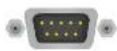
The extenders have RS-232 pass-through function or can be remote controlled through industry standard 9-pole D SUB male connector.
D-sub connector pin assignment for standard RS-232
Pin nr. Pinut
1 NC - non-connected
2 RX data receive (input)
3 TX data transmit (output)
4 DTR (Internally connected to Pin 6)
5 GND signal ground (shield)
6 DSR (Internally connected to Pin 4)
7 RTS (Internally connected to Pin 8)
8 CTS (Internally connected to Pin 7)
9 NC - non-connected
INFO: HDMI20-OPTC-TX/RX220-Pro is DTE unit according to its pin-out. For more information see Serial Management section.
INFO: Factory default settings are the same in the transmitter and receiver. 57600 Baud, 8 bit, 1stop bit, no parity.
3.4. Multimode Single Fiber Extender Concept
HDMI20-CPTC-TX220-Pro and HDMI20-CPTC-RX220-Pro are a HDMI 2.0 compatible single fiber extender pair. They are able to transmit digital video, embedded audio, RS-232 and Gigabit Ethernet signals via multimode optical cable up to 700m. They are designed for rental purposes, supporting uncompressed 4K UHD resolution at 60Hz at 4:4:4 colorspace.
The extenders use only one channel of Neutrik optICON duo cable, and the other channel is internally connected to break-out connector. See details about in Application Example with Break-out Connector section.
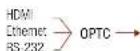
3.4.1. Summary of Interfaces - Transmitter
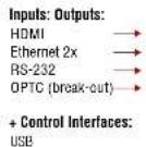
3.4.2. Summary of Interfaces - Receiver
Inputs:
Outputs:
+ Control interfaces: USB
3.5. Optical Interface
HDMI20-OPTC extenders support multimode fiber optical interface to transmit or receive digital video, embedded audio, RS-232 and Ethernet signals. For more details about the supported cable extension distances see Maximum Extension Distances section.
Port Diagram of Optical Interface
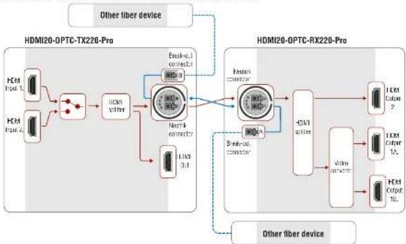
The Neutrik opticalCON DUO cable has two fiber channels, named channel A and channel B. Since Lightware fiber extenders use only one fiber for signal transmission, the other fiber can be used by other optical devices. The unused fiber channel is accessible by the break-out connector.
flowchart
graph TD
    subgraph_HDMI20-OPTC-TX226-Pro["HDMI20-OPTC-TX226-Pro"]
        A1["Input 1"] --> B1["Node"]
        A2["Input 2"] --> B1
        B1 --> C1["HDN core"]
        C1 --> D1["Neural connector"]
        D1 --> E1["Output"]
        D1 --> F1["Breakout"]
        F1 --> G1["Output"]
        G1 --> H1["Neural"]
        H1 --> I1["Output"]
        I1 --> J1["Breakout"]
        J1 --> K1["Output"]
    end

    subgraph_HDMI20-OPTC-RX220-Pro["HDMI20-OPTC-RX220-Pro"]
        L1["Input 1"] --> M1["Node"]
        L2["Input 2"] --> M2["Node"]
        M2 --> N1["HDN core"]
        N1 --> O1["Neural connector"]
        O1 --> P1["Output"]
        P1 --> Q1["Breakout"]
        Q1 --> R1["Output"]
        R1 --> S1["Neural"]
        S1 --> T1["Output"]
        T1 --> U1["Breakout"]
        U1 --> V1["Output"]
    end

    A1 --> B1
    A2 --> B1
    B1 --> C1
    C1 --> D1
    D1 --> E1
    E1 --> F1
    F1 --> G1
    G1 --> H1
    H1 --> I1
    I1 --> J1
    J1 --> K1
    K1 --> L1
    L1 --> M1
    M1 --> N1
    N1 --> O1
    O1 --> P1
    P1 --> Q1
    Q1 --> R1
    R1 --> S1
    S1 --> U1
    U1 --> V1
    V1 --> W1
    W1 --> X1
    X1 --> Y1
    Y1 --> Z1
    Z1 --> AA["Output"]
    AA --> AB["Neural"]
    AB --> AC["Output"]
    AC --> AD["Breakout"]
    AD --> AE["Output"]
    AE --> AF["Neural"]
    AF --> AG["Output"]
    AG --> AH["Breakout"]
    AH --> AI["Output"]
    AI --> AJ["Neural"]
    AJ --> AK["Output"]
    AK --> AL["Breakout"]
    AL --> AM["Output"]
    AM --> AN["Neural"]
    AN --> AO["Output"]
    AO --> AP["Breakout"]
    AP --> AQ["Output"]
    AQ --> AR["Neural"]
    AR --> AS["Output"]
    AS --> AT["Breakout"]
    AT --> AU["Output"]
    AU --> AV["Neural"]
    AV --> AW["Output"]
    AW --> AX["Breakout"]
    AX --> AY["Output"]
    AY --> AZ["Neural"]
    AZ --> BA["Output"]
    BA --> BB["Breakout"]
    BB --> BC["Output"]
    BC --> BD["Neural"]
    BD --> BE["Output"]
    BE --> BF["Breakout"]
    BF --> BG["Output"]
    BG --> BH["Neural"]
    BH --> BI["Output"]
    BI --> BJ["Breakout"]
    BJ --> BK["Output"]
    BK --> BL["Neural"]
    BL --> BM["Output"]
    BM --> BN["Breakout"]
    BN --> BO["Output"]
    BO --> BP["Neural"]
    BP --> BQ["Output"]
    BQ --> BR["Breakout"]
    BR --> BS["Output"]
    BS --> BT["Neural"]
    BT --> BU["Output"]
    BU --> BV["Breakout"]
    BV --> BW["Output"]
INFO: Red line shows the main direction of the video signal. The blue line represents the optical signal via break-out connector, which direction is not specified.
Application Example with Break-out Connector
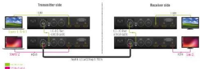
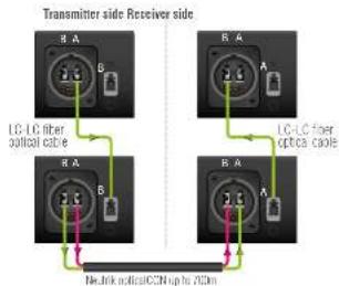
Using this feature, it is possible to transmit two different A/V signal from one transmitter pair to another receiver pair with only one Neutrik opticalCON DUO cable. See the application example below.
text_image
Transmitter side
Source 1 Srl-1
Source 2
HDI
LC-45 fiber
critical cable
Receiver side
LC-6 fiber
critical cable
h34
Sml-2
Width: 0.5mm x 0.8mm x 1.0mm
Transmitter Unit (HDMI20-OPTC-TX220-Pro)
The transmitter's laser driver sends the signal through Channel A. Channel B is directly connected to the break-out connector with a fiber optical cable inside the unit. Any optical signal can be transferred through this channel in any direction.
Receiver Unit (HDMI20-OPTC-RX220-Pro)
The receiver's laser sensor gets the signal through Channel B. Channel A is directly connected to the break-out connector with a fiber optical cable inside the unit. Any optical signal can be transferred through this channel in any direction.
text_image
Transmitter side Receiver side
LG-LC fiber
optical cable
LG-LC fiber
optical cable
Necklink opticalCCN up to 12CM
3.6. Video and Audio Interface
The HDMI20-OPTC series transmitter can receive signal from two types of sources:
• DVI-D
HDMI (with embedded audio)
The HDMI20-OPTC series receiver can output HDMI video signal (with embedded audio).
Port Diagram of Video and Audio Interface
flowchart
graph LR
    A["INPUT 1"] --> C["HDMA Splitter"]
    B["INPUT 2"] --> C
    C --> D["Fiber OUT"]
    D --> E["OUTPUT 2"]
    E --> F["Fiber IN"]
    F --> G["HDMA Splitter"]
    G --> H["OUTPUT 2"]
    H --> I["OUTPUT 1A"]
    G --> J["Video controller"]
    J --> K["Transparent Split"]
    J --> L["Transmitter"]
    K --> M["OUTFUT 1A"]
    L --> N["OUTFUT 1B"]
Transmitter Side
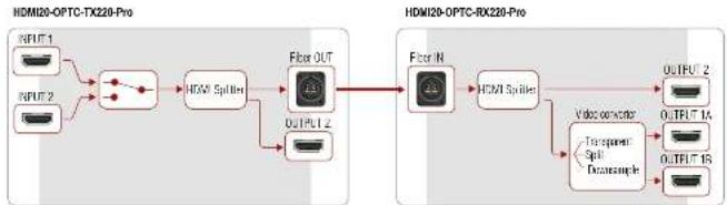
The video signal is received at the Input 1 or the Input 2. The HDMI splitter duplicates the signal and sends the same HDMI stream to the local HDMI output and the fiber output.
Receiver Side
The video and the embedded audio signal arrives via optical cable into the HDMI splitter. It duplicates HDMI stream and transmits the signal without modifying it to the HDMI Out 2 port. The HDMI splitter transmits the same signal into the video converter where three output conversion modes can be set.
3.6.1. Output Conversion Modes
Conversion modes refer to the receiver side and this property can be set in the front panel menu of the transmitter (see Conversion Submenu), available in the Lightware Device Controller Software (see HDMI Output Port - Receiver) and also in the LW3 tree, both the transmitter and the receiver.
In Transparent mode (no conversion mode), the video signal is transmitted to the HDMI Output 1A and the HDMI Output 1B without any changing.
INFO: Maximal data transmission capacity of Output 1B is 9 Gbps, if the video signal is above this bandwidth, there will be no picture on the display.
Split mode means splitting of the original video signal into left and right halves and sending the split signal to the HDMI Output 1A and the HDMI Output 1B.
In Downsample convert mode (convert to YCbCr 4:2:0) the video converter subsamples the 4:4:4 signal to 4:2:0 on the 1A and 1B Output port.
INFO: Split and downsample convert modes are available at maximum 8-bit color depth.
3.6.2. Autoselect Feature
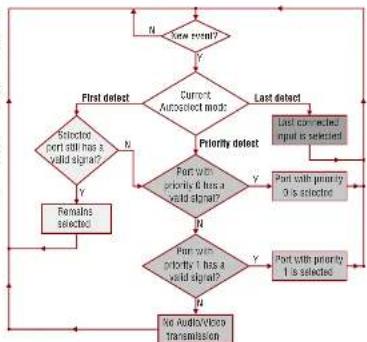
Besides manual crosspoint selection you can choose the Autoselect option on the video ports. There are three types of Autoselect as follows:
First detect mode: selected input port is kept connected to the output while it has an active signal
Priority detect mode: always the highest priority active input is selected to transmit.
Last detect mode: always the last attached input is selected to transmit.
flowchart
graph TD
    A["Start result?"] --> B{Y}
    B -->|N| C["First defect"]
    B -->|Y| D["Current Autocsted mode"]
    D --> E{Priority defect}
    E -->|N| F{Selected port still has a valid signal?}
    F -->|Y| G["Remains selected"]
    F -->|N| H{Port with priority 1 has a valid signal?}
    H -->|Y| I["Port with priority 0 is selected"]
    H -->|N| J{Port with priority 2 has a valid signal?}
    J -->|Y| K["Port with priority 1 is selected"]
    J -->|N| L["No Audio/Vision Transmission"]
    E --> M{Last defect}
    M --> N["Last connected input is selected"]
    N --> O["End"]
Video Interface - Example
flowchart
graph LR
    A["Event master"] -->|HDM IN| B["HDM20-OPTC-TX220-Pro"]
    A -->|DA-D IV| C["PC"]
    C -->|OPIC OUT| B
    B -->|OPIC IN| D["HDM120-OPTC-RX220-Pro"]
    D -->|HDMI OUT| E["Projector"]
The Concept
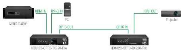
The HDMI signal with embedded audio comes from the Event master to Input 1. The other source is a PC, which sends DVI-D signal to Input 2. Both of them are connected to the transmitter, where the autoselect mode is enabled with priority 0 on the Input 1, so the Input 1 is selected.
INFO: Only one input can be selected at the same time.
Product Overview HDMI20-OPTC series - User's Manual 17
3.7. Control Features
The devices can be controlled over Ethernet, USB, and RS-232 ports as well. The following sections are about to describe the available features and settings by these interfaces.
3.7.1. USB Control Interface
The device can be controlled over front panel USB port (mini B-type connector). This interface supports LW3 protocol. The interface can be used to establish a connection to Lightware Device Controller software.
INFO: USB control operates locally, USB data is not transmitted via optical cable between the transmitter and the receiver.
3.7.2. Ethernet Interface
The device can be controlled via Ethernet port (Neutrik etherCON connector). This interface supports any third-party system controller with LW3 command protocol. The interface can be used to configure the device with Lightware Device Controller and establish the connection to Lightware Device Updater software and perform firmware upgrade.
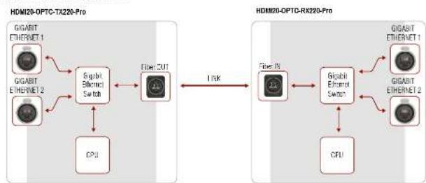
Two Neutrik etherCON connectors provide a wide range of application possibilities:
• Control the device
- Firmware upgrade
• Create a local network
• Daisy chain connection
Port Diagram of Ethernet Interface
flowchart
graph LR
    subgraph HDMI20-OPTC-TX220-Pro
        A["GIGABIT ETHERNET 1"] --> B["6bit Ethernet Switch"]
        C["GIGABIT ETHERNET 2"] --> B
        D["CPU"] --> B
        B --> E["Fiber CUT"]
    end

    subgraph HDMI20-OPTC-RX220-Pro
        F["Fiber 15"] --> G["Gigabit Ethernet Switch"]
        H["Gigabit Ethernet 1"] --> G
        I["Gigabit Ethernet 2"] --> G
        J["CPU"] --> G
        G --> K["1.5K"]
    end
Ethernet Interface - Example
flowchart
graph TD
    A["Hardware Device"] --> B["HDMI0-OPTC-TX220-Pro 1"]
    A --> C["HDMI0-OPTC-TX220-Pro 2"]
    A --> D["HDMI0-OPTC-TX220-Pro 3"]
    A --> E["Computer Laptop"]
    B --> F["HDMI0-OPTC-RX220-Pro 1"]
    B --> G["HDMI0-OPTC-RX220-Pro 2"]
    B --> H["HDMI0-OPTC-RX220-Pro 3"]
    B --> I["Projector 1"]
    B --> J["Projector 2"]
    B --> K["Projector 3"]
    B --> L["Projector 4"]
    B --> M["Projector 5"]
    B --> N["Projector 6"]
    style A fill:#f9f,stroke:#333
    style B fill:#ccf,stroke:#333
    style C fill:#ccf,stroke:#333
    style D fill:#ccf,stroke:#333
    style E fill:#ccf,stroke:#333
    style F fill:#cfc,stroke:#333
    style G fill:#cfc,stroke:#333
    style H fill:#cfc,stroke:#333
    style I fill:#cfc,stroke:#333
    style J fill:#cfc,stroke:#333
    style K fill:#cfc,stroke:#333
    style L fill:#cfc,stroke:#333
    style M fill:#cfc,stroke:#333
Transmitters are connected to each other via LAN, the receivers connected to the transmitters via optical fiber and all the projectors connected to the receivers via LAN.
This way the Laptop can control the system with Ethernet commands:
INFO: HDMI20-OPTC-TX/RX220-Pro are DTE unit according to their pin-out. For more details about pin assignment see RS 232 Port section.
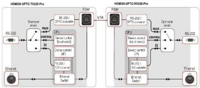
Serial data communication can be established via local RS-232 port (D-SUB male connector). Three different RS-232 modes can be set for the serial port: pass-through mode, control mode, command injection mode, see the figure below.
Port Diagram of Serial Interface
flowchart
graph LR
    subgraph HDMI20-OPTC-TX220-Pro
        A["RS-232"] --> B["Operator mode"]
        B --> C["CPU"]
        C --> D["Device control (local serial)"]
        D --> E["Device control (IF)"]
        E --> F["RS-232 / TCP controller"]
        F --> G["Ethernet Switch"]
        G --> H["Fiber"]
        H --> I["Link"]
        I --> J["RF"]
    end

    subgraph HDMI20-OPTC-RX220-Pro
        K["RS-232"] --> L["Operator mode"]
        L --> M["CPU"]
        M --> N["Device control (local serial)"]
        N --> O["Device control (IF)"]
        O --> P["RS-232 / TCP controller"]
        P --> Q["Ethernet Switch"]
        Q --> R["Fiber"]
        R --> S["Link"]
        S --> T["RF"]
    end

    B <-->|PASS| M
    M <-->|CONTROL| N
    N <-->|CI| O
    O <-->|CI| P
    P <-->|CI| Q
    Q <-->|CI| R
    R <-->|PASS| S
    S <-->|CONTROL| T
    T <-->|CI| U["RF"]
    U --> V["Ethernet Switch"]
    V --> W["Fiber"]
    W --> X["RF"]
    X --> Y["Operation mode"]
    Y --> Z["RS-232"]
The following operation modes are defined:
PASS: The local serial port is in Pass-through mode.
• CONTROL: The local serial port is in Control mode.
Cl: The local serial port is in Command Injection mode.
Pass-through Mode
In pass-through mode, the given device forwards the data that is coming from one of its ports to another same type of port. The command is not processed by the CPU. Incoming serial data is forwarded from one port to another port.
ATTENTION! Both the transmitter and the extender have to be set Pass-through mode, in case of sending RS-232 commands from the TX side to the third party device on the RX side.
Control Mode
The incoming data from the given local port is processed and interpreted by the CPU. The mode allows to control the extender directly. LW3 protocol commands are accepted.
Command Injection Mode
In this mode, the extender works as a TCP/IP <-> RS-232 bidirectional converter. The TCP/IP data signal is converted to RS-232 data and vice versa. TCP/IP port numbers are defined for the serial ports for this purpose. E.g. the default Command Injection port number of the local RS-232 port is 8001.
INFO: The commands in this mode not transmitted via fiber, they operates between the local ports.
RS-232 Signal Transmission - Example 1
flowchart
graph TD
    A["RS-232 FIBER OPTICAL RS-232"] --> B["System controller"]
    A --> C["HDMI20-CPTC-TX220-Pro transmitter"]
    A --> D["HDMI20-CPTC-RX220-Pro receiver"]
    A --> E["Projector"]
The Concept
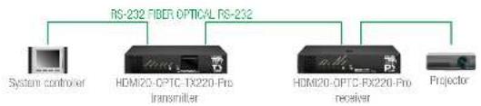
You can control the Projector over the extenders with the System controller. The controller is connected to the local RS-232 port of the Transmitter which transmits the signal toward the Receiver over the fiber optical line. The Projector is connected to the local RS-232 port of the Receiver. The serial connection is bidirectional which means the controller gets back the responses of the projector.
In this case the RS-232 port of the transmitter and receiver has to be set to Pass-through mode.
4
Operation
This chapter is about the powering and operating of the device describing the functions which are available by the front/rear controls:
POWERING ON
▶ FRONT PANEL OPERATIONS
▶ FRONT PANEL LCD MENU OPERATIONS
4.1. Powering on
Connect the power cord to the AC input connector; the extender is immediately powered on. After the self-test, the last configuration is loaded automatically.
4.2. Front Panel Operations
ATTENTION! When Dark mode is enabled, no LEDs are on, even though the device is fully functional.
Status LEDs - Transmitter
POWER/LIVE FRONT
green
blinking
The transmitter unit is powered and ready to use.
green
on The transmitter unit is out of operation.
off The transmitter unit is NOT powered or out of operation.
FIBER LINK FRONT
green
on The connection is established between the transmitter and the receiver and they can communicate to each other.
off When the TX and RX are not connected.
yellow
blinking
It shows connection error in the RX and TX.
HDCP FRONT
green
on Video signal is HDCP encrypted.
off There is no HDCP encryption in the video signal.
yellow
blinking
It shows HDCP error.
INPUT1, INPUT2 FRONT
green
on This port is selected and there is a valid video signal on it.
green
blinking
When the port is selected and there is no valid video signal on it.
yellow
on
When the port is not selected, but there is a valid video signal on it.
off This port is not selected and there is no signal on it.
Status LEDs - Receiver
POWER/LIVE FRONT
green
blinking
The receiver unit is powered and ready to use.
○
off
The receiver unit is NOT powered or out of operation.
FIBER LINK
FRONT
green
on
The connection is established between the transmitter and the receiver and they can communicate to each other.
○
off
When the TX and RX are not connected.
○
yellow
blinking
It shows connection error in the RX and TX.
HDCP
FRONT
green
on
Video signal is HDCP encrypted.
○
off
There is no HDCP encryption in the video signal.
○
yellow
blinking
It shows HDCP error.
SIGNAL PRESENT
FRONT
green
on
Valid video signal is present.
○
off
No video signal is present.
○
yellow
blinking
It shows error in the video signal transmission.
OUTPUT CONVERSION
FRONT
green
on
Split mode is active.
○
off
Transparent mode (no conversion) is active.
○
yellow
on
Downsample convert (convert to YCbCr 4:2:0) mode is active.
LASER ACTIVE
REAR
red
on
It gives feedback about the operation of the optical module, that means the laser radiates invisible waves. Avoid direct eye contact with the optical connectors!
○
off
Laser modul is not active.
INFO: When LEDs blink green three times after clicking on the Input/Function button, they show that the front panel lock is enabled.
Operation HDMI20-OPTC series - User's Manual 20
4.2.1. Function Button - HDMI20-OPTC-TX220-Pro
Select button is for switching between the Input 1 and the Input 2.
Autoselect mode can not be activated by pushing the Select button, but this function can be disabled by choosing Input 1 or Input 2 with the Select button.
INFO: Autoselect mode can be set with Lightware Device Controller software (see HDMI Output Port - Transmitter and Optical Output Port - Transmitter section) or with protocol commands (see Changing the Autoselect Mode section).
Enable Dynamic (DHCP) IP Address
The device gets a static IP address as a factory default setting. If this setting does not fit to the circumstances during install or usage, DHCP* can be enabled from the front panel:
Step 1. Make sure the device is powered on and operational.
Step 2. Press and keep pressed the Select button for 5 seconds.
Step 3. After 5 seconds front panel LEDs start blinking; release the button and press it 3 times again quickly (within 1,5 seconds).
Step 4. The LEDs get dark, DHCP gets enabled.
Step 5. As a final step, device restarts and is available with the new IP address.
* Static IP address also can be modified. This setting is available on the front panel menu or in Lightware Device Controller software.
Restore Factory Default Settings
To restore factory default values, do the following steps:
Step 1. Make sure the device is powered on and operational.
Step 2. Press and keep pressed the Select button for 10 seconds. After 5 seconds front panel LEDs start blinking but keep on pressing the button.
Step 3. After 5 seconds the blinking gets faster; release the button and press it 3 times again quickly (within 1,5 seconds).
Step 4. The LEDs get dark, the device restores the factory default settings and reboots.
Factory default settings are listed in the Factory Default Settings section.
4.2.2. Boot Button
Hidden button for special bootload function. Use only for the particular request of the Lightware Support Team.
4.2.3. Function Button - HDMI20-OPTC-RX220-Pro
Function button sets the output conversion mode. See details about these modes in Output Conversion Modes section.
Enable Dynamic (DHCP) IP Address
The device gets a static IP address as a factory default setting. If this setting does not fit to the circumstances during install or usage, DHCP can be enabled from the front panel:
Step 1. Make sure the device is powered on and operational.
Step 2. Press and keep pressed the Function button for 5 seconds.
Step 3. After 5 seconds front panel LEDs start blinking; release the button and press it 3 times again quickly (within 1,5 seconds).
Step 4. The LEDs get dark, DHCP gets enabled.
Step 5. As a final step, device restarts and is available with the new IP address.
* Static IP address also can be modified. This setting is available on the front panel menu or in Lightware Device Controller software.
Restore Factory Default Settings
To restore factory default values, do the following steps:
Step 1. Make sure the device is powered on and operational.
Step 2. Press and keep pressed the Function button for 10 seconds. After 5 seconds front panel LEDs start blinking but keep on pressing the button.
Step 3. After 5 seconds the blinking gets faster; release the button and press it 3 times again quickly (within 1.5 seconds).
Step 4. The LEDs get dark, the device restores the factory default settings and reboots.
Factory default settings are listed in the Factory Default Settings section.
4.2.4. Boot Button
Hidden button for special bootload function. Use only for the particular request of the Lightware Support Team.
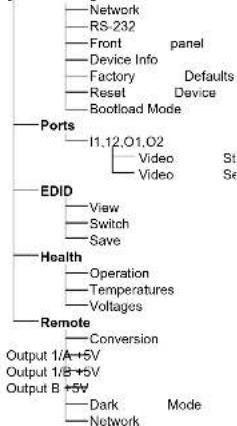
4.3. Front Panel LCD Menu Operations
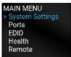
The front panel has a color LCD that shows the most important settings and parameters structured in a menu. The jog dial control knob can be used to navigate between the menu items or change the value of a parameter. The knob can be pressed to enter a menu or edit/set a parameter.
Menu navigation & change parameter
Menu selection & set parameter
system Settings
flowchart
graph TD
    A["Network"] --> B["RS-232"]
    B --> C["Front panel"]
    C --> D["Device Info"]
    D --> E["Factory Defaults"]
    E --> F["Reset Device"]
    F --> G["Bootload Mode"]
    H["Ports"] --> I["I1.12,O1,O2 Video State"]
    H --> J["Video State"]
    K["EDID"] --> L["View Switch Save"]
    K --> M["Operation Temperatures Voltages"]
    N["Health"] --> O["Operation Temperatures Voltages"]
    N --> P["Conversion Conversion Output 1/A+5V Output 1/B+5V Output B+5V Dark Mode Network"]
Parameter Selection
The blue colored line means the selected menu/parameter, the green one means the current setting.
TIPS AND TRICKS: The faster you rotate the jog dial, the faster the parameter list is scrolled.
4.3.1. System Settings Menu
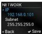
Network Submenu
The parameters of the network connection can be set in this submenu. IP, Subnet, Gateway and MAC parameters show the current settings. If the DHCP option is disabled, three more parameters are listed which can be set for a static IP address:
Static IP
Static Subnet.
Static Gateway.
ATTENTION! If you change the network settings, always press the Save option under Network menu (not only in the submenu of the parameter) to apply the new settings.
The following front panel-related parameters can be set in this submenu:
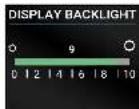
• Display Backlight (1-10)
The brightness of the LCD can be set from 1 to 10 on a scale.
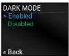
• Dark Mode (Enabled/ Disabled)
All the LEDs and the background light of the LCD on the transmitter unit are turned off 60 s after enabling the dark mode.
TIPS AND TRICKS: Press any buttons or turn the jog dial knob to 'wake up' the device. The first contact activates the LEDs and LCD and does not execute the original function.
INFO: The setting of the dark mode in the receiver is available in the Remote Menu.
• Rotary Direction (CW Down/ CCW Down)
Device Info Submenu
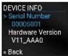
In this submenu you can check basic information about the transmitter unit:
Serial number
Hardware Version
Firmware Version
• Video MCU #1
• Video MCU #2
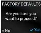
Factory Defaults Submenu
Factory default settings will be restored by choosing Yes.
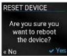
Reset Device Submenu
There is a possibility to reset the device.
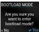
Bootload Mode Submenu
Special function for entering the bootload mode.
4.3.2. Ports Menu
When entering the menu the available video input and output ports are listed. The icons display information about the port and the video signal (see below table). Select the desired port and enter to see the submenu.
PORTS
>11
12
01
02
< Back
Grey icon
Description
White icon
Description
Source/sink is not connected
Source/sink is connected
No audio signal in the video stream
Audio is embedded in the video stream
Signal is not present
Signal is present
Signal is not encrypted with HDCP
Signal is encrypted with HDCP
The port is unmuted
The port is muted
Video Status Submenu for Input Ports
The most important status information can be seen of the chosen input port.
The table below relates to the input ports of both the transmitter and receiver.
The most important status information can be seen of the chosen output port.
The table below relates to the output ports of both the transmitter and receiver.
VIDEO STATUS
> Hotplug detect
Present
Signal Present
Present
« Back
Parameter 01 (OPTOUT) 02 (HDMIOUT)
Hotplug detect
Present/ Not present Present/ Not present
Signal Present
Present/ Not present/Unknown
Present/ Not present/Unknown
HDCP Status
none/ HDCP 1.4/HDCP 2.2
none/ HDCP 1.4/ HDCP 2.2
HDCP capability
- none/ HDCP 1.4/ HDCP 2.2
Embedded Audio
Present/ Not present/Unknown
Present/ Not present/Unknown
Pixel Clock (MHz)
No signal [x] MHz No signal [x] MHz
Active Resolution
Unknown/ No signal[x|x|y][\p][f]
Unknown/ No signal[x|x|y][\p][f]
Total Resolution
Unknown/ No signal/[x|x|y]
Unknown/ No signal/[x|x|y]
Video Settings Submenu for Output Ports
• Signal Type (Auto / DVI)
- +5V Enable (Always on / Always off / Auto)
• HDCP Mode (Auto / Always on)
VIDEO SETTINGS
> Signal Type
Auto
+5V Enable
Always on
< Back
4.3.3. EDID Menu
Advanced EDID Management is available in the front panel LCD menu which allows to view an EDID, switch, or save it to the User EDID memory. See more information about EDID technology in EDID Management. The EDID memory structure of the device can be found in Sources and Destinations chapter.
View Submenu
Select the desired EDID memory block: Factory EDIDs, Last Attached EDIDs, User EDIDs, or Emulated EDIDs. Select the Name item and press the knob. Use the jog dial to step between the EDIDs. The following information can be checked:
Preferred Resolution
Monitor Name
• Audio Info
Switch Submenu
The submenu looks similar to the View submenu but in this case, the Destination is also listed. To change an EDID do the followings:
Step 1. Navigate to the EDID/Switch submenu.
Step 2. Select the Name item and press the knob. Use the jog dial to select the desired EDID (F1-F146, U1-U14, or D1-D
Step 3. Select the Destination item and press the knob. Use the jog dial to select the desired EDID memory (E1, E2, All) and press the knob.
Step 4. Navigate to the Switch option and press the knob.
Save Submenu
The EDID of a connected sink can be saved to the User EDID memory as follows:
Step 1. Navigate to the EDID/Save submenu.
Step 2. Select the Name item and press the knob. Use the jog dial to select the desired EDID (D1-D2*) and press the knob.
Step 3. Select the Destination item and press the knob. Use the jog dial to select the desired EDID memory (U1-U14) and press the knob.
Step 4. Navigate to the Save option and press the knob.
* D1 is for Optical output and D2 is for local HDMI output.
Operation HDMI20-OPTC series - User's Manual 23
4.3.4. Health Menu
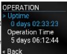
Operation Submenu
The following information is displayed about the transmitter unit in this menu:
- Uptime: the elapsed time since the last booting.
• Operation time: displays the summary of the operation hours.
Temperatures Submenu
This submenu gives a feedback about the current temperatures of the internal parts in the unit:
- CPU / System / Air intake / Video chip / Ethernet switch / Video MCU #1 / Video MCU #2.
Voltages Submenu
The following information is displayed in Voltages Submenu:
- Main 5V / Main 3.3V, Video IC #11.3V V/1 / Video IC #11.3V V/2 / Video IC #2 1.3V/1 / Video IC #2 1.3V/2
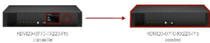
4.3.5. Remote Menu
ATTENTION! This settings related to the connected receiver.
Adjustable parameters of the receiver:
Conversion Submenu
The following conversion modes can be set in the receiver:
- Off
• YUV 4:2:0
- Split left/right
- Split ri
See more details about this mode in Output Conversion Modes section.
All the LEDs on the receiver unit are turned off 60 seconds after enabling the dark mode. Waking up the device is available by disabling the dark mode.
Network Submenu
The parameters of the receiver's network connection can be set in this submenu. IP, Subnet, Gateway and MAC parameters show the current settings. If the DHCP option is disabled, three more parameters are listed which can be set for a static IP address:
Static IP,
Static Subnet,
Static Gateway
ATTENTION! If you change the network settings, always press the Save option under Network menu (not only in the submenu of the parameter) to apply the new settings.
5
Software Control – Using Lightware Device Controller
The extender can be controlled by a computer through the LAN, RS-232 and USB ports using Lightware Device Controller (LDC). The software can be installed on a Windows PC or Mac OS X. The application can be downloaded from www.lightware.com. The Windows and the Mac versions have the same look and functionality.
▶ OVERVIEW
THE TREE STRUCTURE
LW3 COMMANDS
▶ FORMAL DEFINITIONS
▶ SYSTEM COMMANDS
▶ VIDEO PORT AND CROSSPOINT SETTINGS
▶ NETWORK CONFIGURATION
RS-232 PORT CONFIGURATION
- SENDING MESSAGE VIA THE COMMUNICATION PORTS
▶ EDID MANAGEMENT
LW3 COMMANDS - QUICK SUMMARY
5.1. Install and Upgrade
INFO: After the installation, the Windows and the Mac application has the same look and functionality.
Installation for Windows OS
Run the installer. If the User Account Control drops a pop-up message click Yes.
During the installation you will be prompted to select the type of the installation: normal and the snapshot install:
Normal install Snapshot install
Available for Windows and Mac OS X Available for Windows
The installer can update only this instance Cannot be updated
Only one updateable instance can exist for all users
More than one different version can be installed for all users
Comparison of installation types
ATTENTION! Using the Normal install as the default choice is highly recommended.
Installation for Mac OS X
Mount the DMG file with double clicking on it and drag the LDC icon over the Applications icon to copy the program into the Applications folder. If you want to copy the LDC into another location just drag the icon over the desired folder.
INFO: The MAC installer is equal with the Normal install in case of Windows and results an updatable version with the same attributes.
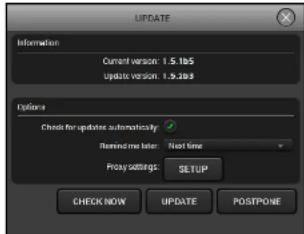
Upgrading of LDC
Step 1. Run the application.
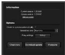
The Device Discovery window appears automatically and the program checks the available updates on Lightware's website and opens the update window if the LDC found updates.
The current and the update version number can be seen at the top of the window and they
are shown in this window even with the snapshot install.
The Update window can also be opened by clicking the About icon and the Update button.
Set the desired update setting in the Options section.
- If you do not want to check for the updates automatically, uncheck the circle, which contains the green tick.
- If you want to postpone the update, a reminder can be set with different delays from the drop down list.
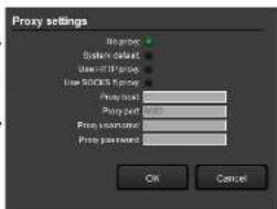
If the proxy settings traverse the update process, set the proper values then click the OK button.
Step 2. Click the Download update button to start the upgrading.
The updates can be checked manually by clicking the Check now button.
5.2. Establishing the Connection
Step 1. Connect the device to a computer via USB, RS-232 or Ethernet.
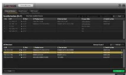
Step 2. Run the controller software; device discovery window appears automatically.
Software Control - Using Lightware Device Controller HDMI20-OPTC series - User's Manual 25
Step 3. Select the unit from the discovered Ethernet devices or under USB devices; when the device is connected through RS-232 click on the Query button next to the desired serial port to display the device's name and serial number. Double click on the receiver or select the device and click on the Connect button.
ATTENTION! When the device is connected via the local RS-232 port, make sure that Control mode and LW3 protocol are set on the serial port.
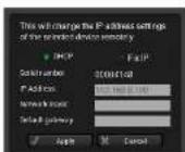
Change IP Address
To modify IP address settings quickly it is not necessary to enter the device's settings/network menu, you can set them by clicking the pencil icon beside the IP address. In this window you can see only the new settings.
Identifying the Device
Clicking on the icon results the blinking of the LDC screen for 10 seconds. The feature helps to identify the device itself in the rack shelf.
5.3. Crosspoint Menu - HDMI20-OPTC-TX220-Pro
Video tab
text_image
LIGHTWARE
H2428NPTG1F220P30
Image
LCD
Control
Storage
Video
LPG
VPS
HDMI
3D
Layer TypeLogo
Advanced Web
Video Tab in Crosspoint Menu
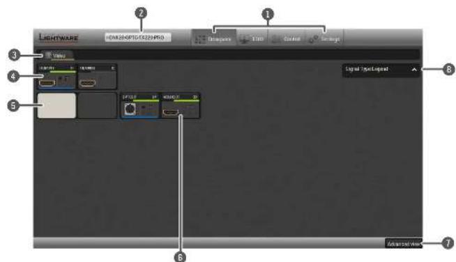
Main menu The available menu items are displayed. The active one is shown with dark grey background color.
2 Information ribbon It shows the device label which can be edited in the Settings menu - Status Tab. A drop-down menu is displayed by clicking on this ribbon. You can turn back to the Device Discovery Window or open the connected TX or RX in a new window (if it is in the same LAN).
3 Tab selector ribbon Submenu selection by clicking on the tab.
4 Input ports Click on the port to open the Port properties window.
5 Connections Light grey square means the port is available but there is no connection between the input and the output. White square means there is a connection between the input and the output port.
6 Output ports Click on the port to open the Port properties window.
Advanced view Click on the button to display the Advanced view page. It shows the Terminal window and the LW3 protocol tree.
③ Legend panel The applied colors of the input/ output ports are described in this panel.
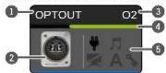
Port Tiles
The colors of the port tiles and the displayed icons represent different states and information:
State Indicators
1 Port name
2 Port icon
3 Port number
4 Signal present indicator
green: present / grey: not present
5 State Indicators
Icon
Icon is grey Icon is black
Source/sink is not connected
Source/sink is connected (+5V / Hotplug detected)
Audio is not embedded in the video stream
Audio is embedded in the video stream
Port is unmuted Port is muted
HDCP encryption is not enabled
HDCP encryption is enabled
Icon
Icon is grey
Icon is green
A
Autoselect setting is disabled
Autoselect setting is enabled
Software Control - Using Lightware Device Controller HDMI2C-OPTC series - User's Manual 26
5.4. Port Properties Window
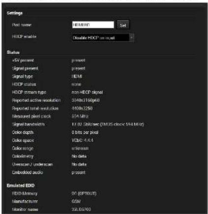
5.4.1. HDMI Input Port -Transmitter
By clicking on one of the HDMI input tile, the most important video related information and settings are available in the port properties window.
text_image
Settings
Post number: 80000000
Set
H10P mode: Double H10P on input
Status
+5V percent present
Signal present present
Signal type HCM
H10P status none
H10P stream type non-H10P signal
Reported active resolution 394Hz(16)g/8
Reported total read count 460Hz(250)
Measured pixel clock 654 MHz
Signal bandwidth 17.92 KB/sec (TMUS clock 194 MHz)
Color depth 0 bits per pixel
Color space YOCC 4.4.4
Color range unknown
Calcimetry No data
Overscan / underscam No data
Embedded audio present
Emulated EIOX
EIOX Memory D:\GPTOUT\T
Manufacturer GSM
Monitor name 32.05760
Available Settings:
Port name
- HDCP Enable (Disable HDCP input / Allow HDCP 1.4 only / Allow HDCP 2.2 and HDCP 1.4).
Port number max. HDCP version
I1 HDCP 2.2
I2 HDCP 1.4
- Reloading factory defaults (see more details in Factory Default Settings section).
INFO: Factory default settings have not effect on the emulated EDID.
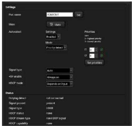
5.4.2. HDMI Output Port - Transmitter
Click on the local HDMI output port to open the port properties window. The most important information and settings are available from the panel.
text_image
Settings
Port name: EOMOUT Set
Mode: None
Autoselect Settings
Realized
Mode:
Fronty detect
Priorities
um
a - highest priority
b - lowest priority
I1 0
I2 1
Set priorities
Signal type: Auto
HV enable: Always on
HOP mode: Depends on Input
Status
Routing defect not corrected
Signal present present
Signal type HODR
HOP status none
HOP stream type non-HOP signal
HOP capability none
Available settings:
• Change the name of the port;
- Mute/unmute the port;
- Autoselect settings: enable / disable, mode, and priorities. (See more details in Autoselect Feature section)
• Auto/DVI/HDMI signal type;
- Enabling the +5V: Auto / Always on / Always off;
• HDCP mode: Depends on input / Maximum possible
Depends on input: The encryption level depends on the settings of the input port and the source content/device. If the incoming signal is not encrypted, then the outgoing signal will not be encrypted either.
Maximum possible: The highest supported level of encryption.
• Factory default settings for the selected port.
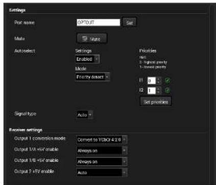
Optical Output Port - Transmitter
text_image
Settings
Port name: OPTOUT Set
Multi Mode
Autoselect Settings
Enabled
Mode
Fronty detect
Priorities
Run:
2. Rightward proxy
1 - lowest priority
11 0
12 0
Set priorities
Signal type Auto
Receiver settings
Output 1 conversion mode Convert to YB@F 4.2.0
Output 1/A +5V enable Always on
Output 1/B +5V enable Always on
Output 2 +5V enable Auto
Available settings (related to the transmitter):
Change the name of the port;
Mute/unmute the port;
Autoselect settings: enable / disable, mode, and priorities. This setting is always the same on both outputs. (See more details in Autoselect Feature section)
• Auto/DVI/HDMI signal type;
• Factory default settings for the selected port.
Available settings (related to the receiver):
Output 1 conversion mode: No conversion / Convert to YCbCr 4.2.0 / Split A: left, B: right / Split A: right, B: left. For more information see Output Conversion Modes section.
• Output 1/A +5V enable: Auto / Always on / Always off
• Output 1/B +5V enable: Auto / Always on / Always off
• Output 2 +5V enable: Auto / Always on / Always off
Software Control - Using Lightware Device Controller HDMI2C-OPTC series - User's Manual 27
5.4.3. Optical Input Port - Receiver
text_image
Input 1 - OPTIN
Settings
Port name: OPTIN Set
Status
Remote device present present
Signal present present
Signal type HDMI
HDCP status none
HDCP stream type non-HDCP signal
Reported active resolution 3540x2160p60
Reported total result on 4400x2250
Measured pixel clock 6814 Hz
Signal bandwidth 17/82 Shift/sec (TMOS clock 69.4 MHz)
Color depth 8 bits per pixel
Color space VCDI-644
Color range unknown
Color entry No data
Duration / undercase No data
Embedded audio present
Emulated EXO
EXO Memory D1 (HDMIOUTLA)
Manufacturing OSM
Monitor name 32.05700
Preferred resolution 1920x1080p650Hz
Other
Factory defaults Refused
Available Settings:
- Port name;
- Reloading factory defaults (see factory default settings in the Factory Default Settings section).
INFO: Factory default settings have not effect on the emulated EDID.
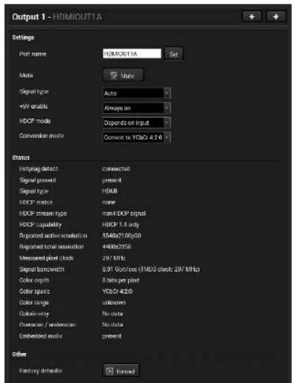
5.4.4. HDMI Output Port - Receiver
text_image
Output 1 - HDMIOUTTA
Settings
Port name: HDMIOUTTA Set
Mode: Mode
Signal type: Auto
+0V enable: Always on
HDCP mode: Depends on input
Conversion mode: Convert to YC60/42.0
Status
Inertarget detect: Connected
Signal present: present
Signal type: HDMI
HDCP status: none
HDCP stream type: non-HDCP signal
HDCP capability: HDCP 1.4 only
Reported action resolution: 3840x210fps50
Reported total resolution: 4400x2250
Measured pixel clock: 297 MHz
Signal bandwidth: 8.91 GHz/sec (TMOS clock: 297 MHz)
Color depth: 8 bits per pixel
Color space: YC60/4200
Color range: unknown
Colonying: No data
Overpass / undescan: No data
Embedded audio: present
Other
Factory details:
Returned
Available Settings:
Change the name of the port;
Mute/unmute the port;
• Auto/DVI/HDMI signal type;
Enabling the +5V: Auto / Always on / Always off
• HDCP mode: Depends on input / Maximum possible
Depends on input: The encryption level depends on the settings of the input port and the source content/device. If the incoming signal is not encrypted, then the outgoing signal will not be encrypted either.
Maximum possible: The highest supported level of encryption.
• Output 1 conversion mode: No conversion /
Convert to YCbCr 4:2:0 / Split A: left, B: right / Split A: right, B: left.
INFO: Conversion mode setting effects only on HDMIOUT1A (01) and HDMIOUT1B (02) port, so HDMIOUT2 (03) port does not have not this setting.
- Factory default settings for the selected port.
Software Control - Using Lightware Device Controller HDMI20-OPTC series - User's Manual 28
5.5. EDID Menu
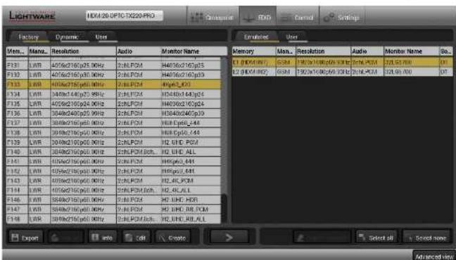
Advanced EDID Management can be accessed by selecting the EDID menu. There are two panels: left one contains Source EDIDs, right one contains Destination slots where the EDIDs can be emulated or copied.
Opening Advanced EDID Editor with the selected EDID
Opening Easy EDID Creator
Executing EDID emulation or copying (Transfer button)
Deleting EDID (from User memory)
Selecting all memory places in the right panel
Selecting none of the memory places in the right panel
5.5.1. Sources and Destinations
The EDID memory consists of four parts:
Factory EDID list (F1-F146) the pre-programmed EDIDs, see the Factory EDID List in the Appendix section.
Dynamic EDID list (D1-D2): the EDID of the last attached display device. The extender stores the last EDID from the previously connected sink on each output port. Thus, an EDID can be shown even if there is no device is connected to the output port at that moment.
User memory locations (U1 - U14): they can be used to save custom EDIDs. Any EDID from the User/Factory/Dynamic EDID lists can be copied to the user memory.
Emulated EDID list (E1-E2): the currently emulated EDID for the input. The source column displays the memory location that the current EDID was routed from. The source reads the EDID from the Emulated EDID memory on the input port.
There are two types of emulation: static and dynamic.
Static EDID emulation: an EDID from the Factory or User EDID list is selected. Thus, the Emulated EDID remains the same until the user emulates another EDID.
Dynamic EDID emulation: it can be enabled by selecting D1-D2 EDID memory. The attached monitor's EDID is copied to the input; if a new monitor is attached to the output, the emulated EDID is changed automatically.
INFO: The default emulated EDID is D1 both the transmitter and the receiver. The EDID, which is from the attached monitor of HDMIOUT1A (01) port of the receiver, is copied to all the input ports.
5.5.2. EDID Operations
Changing the Emulated EDID
Step 1. Choose the desired tab (Factory, Dynamic, or User EDID list) on the left panel and select an EDID.
Step 2. Select the Emulated lab on the right panel.
Step 3. Select the target port on the right panel (one or more ports can be selected); the EDID(s) will be highlighted with a yellow cursor.
Step 4. Press the Transfer button to change the emulated EDID.
Learning an EDID
The process is the same as changing the emulated EDID; the only difference is the Destination panel: press the User button. Thus, one or more EDIDs can be copied into the user memory either from the factory memory or from a connected sink (Dynamic).
Exporting an EDID
Source EDID can be downloaded as a file (*.bin, *.dat or *.edid) to the computer.
Step 1. Select the desired EDID from the left panel (the line will be highlighted with yellow).
Step 2. Press the Export button to open the dialog box and save the file to the computer.
Software Control - Using Lightware Device Controller HDMI2C-OPTC series - User's Manual 29
Importing an EDID
Previously saved EDID (*.bin, *.dat or *.edid file) can be uploaded to the user memory:
Step 1. Select the User tab in the left panel and select a memory slot.
Step 2. Press the Import button below the Source panel.
Step 3. Browse the file in the opening window then press the Open button. Browsed EDID is imported into the selected User memory.
ATTENTION! The imported EDID overwrites the selected memory place even if it is not empty.
Deleting EDID(s)
The EDID(s) from User memory can be deleted as follows:
Step 1. Select the User tab in the left panel.
Step 2. Select the desired memory slot(s); one or more can be selected (Select all and Select None buttons can be used). The EDID(s) will be highlighted with yellow.
Step 3. Press the Deleted selected button to delete the EDID(s).
5.5.3. EDID Summary Window
Select an EDID from Source panel and press the Info button to display EDID summary.
text_image
General
Power Management
Gamma / Colors
Established Timings
Standard Timings
Preferred Timing Mode
2nd Descriptor Field
3rd Descriptor Field
4th Descriptor Field
CEA General
CEA Video
CEA Audio
CEA Speaker Allocation
CEA HDMI VSDB
CEA HDMI Forum VSDB
CEA YCbCr 4:2.0 YCB
CEA YCbCr 4:2.0 Capability Map
CEA Colorimetry
CEA High Dynamic Range
CEA Detailed Timing Descriptors
General
EDID version: 1
EDID revision: 3
Manufacturer ID: GSM (Goldstar Company Ltd)
Product ID: 085B
Monitor serial number: 356928
Year of manufacture: 2017
Week of manufacture: 3
Signal interface: Digital
Separate Sync H&V:
Composite sync on H:
Sync on green:
Seration on VS:
Color depth: Undefined
Interface standard: Not defined
Color spaces: RGB 4:4:4 & YCrCb 4:4:4
Aspect ratio: 0.57
Display size: 60 cm X 34 cm
Import
5.5.4. Editing an EDID
Select an EDID from the left panel and press the Edit button to display Advanced EDID Editor window. The editor can read and write all descriptors, which are defined in the standards, including the additional CEA extension. Any EDID from the device's memory or a saved EDID file can be loaded into the editor. The software resolves the raw EDID and displays it as readable information to the user. All descriptors can be edited, and saved in an EDID file, or uploaded to the User memory. For more details about EDID Editor please visit our website (www.lightware.com) and download the EDID Editor User's Manual.
text_image
Basic EIO
Vendor / Product Information
Display Parameters
Power Management and Features
Gamma / Color and Established Timings
Standard Timings
Preferred Timing Mode
2nd Descriptor Field
3rd Descriptor Field
4th Descriptor Field
CEA Extension
General
Video Data
Audio Data
Speaker Allocation Data
HDMI VSOB
HDMI Forum VSOB
VCBO 4:2.0 VDB
VCBO 4:2.0 Capability Map
Colorimetry
High Dynamic Range
Detailed Timing Descriptor #1
Detailed Timing Descriptor #2
Detailed Timing Descriptor #3
Detailed Timing Descriptor #4
Detailed Timing Descriptor #5
Detailed Timing Descriptor #6
Save EIO
Software Control - Using Lightware Device Controller HDMI2C-OPTC series - User's Manual 30
5.5.5. Creating an EDID
Since above mentioned Advanced EDID Editor needs more complex knowledge about EDID, Lightware introduced a wizard-like interface for fast and easy EDID creation. With Easy EDID Creator it is possible to create custom EDIDs in four simple steps. By clicking on the Create button below the left panel, Easy EDID Creator is opened in a new window.
text_image
Select Resolution & Interface
Video Format
Audio Format
Finish
Next
Select Resolution & Interface
Welcome to the Easy EDID Creator!
With this software you are able to create a unique EDID according to your demands.
Details can be added or changed in the Advanced EDID Editor later if needed.
Please select the format type and the preferred resolution. If you don't find the proper
mode in the list, use the Custom format type setting, enter the resolution and the
program will estimate the best blanking times.
Important notes:
• If you want to send audio then you must select HDMI or DisplayPort. DVI and VGA
do not support audio transmission.
• Most DVI displays are not able to process HDMI signals. If you have a DVI display,
please check its specifications.
• The supported color depth will be 24bits/pixel by default.
Format type: Broadcast
Resolution: 640x480p60
Interface type: VGA DVI
HDMI DisplayPort
Easy EDID Creator Wizard
5.6. Control Menu
5.6.1. RS-232 Tab
text_image
LIGHTWARE
H01-20-OP10-0520-FR3
Crosspoint
TBD
Control
Settings
RS-229
Chatter
Events
F1
RS-232 tab in Control menu
The following settings and functions are available on the local RS-232 port:
Port name
Operation mode: Pass-through, Control, Command Injection, (for more details see Serial Interface section);
Command injection: enable or disable;
• Command injection port number;
• Control protocol: LW2 or LW3;
Message sending via serial port;
Reloading factory defaults (see the Factory Default Settings section).
text_image
Port 1 - LOCAL
Settings
Port name: LOCAL Set
Operation mode: Passthrough
Pursit rate: $7500
Data bits: 0
Pulsity: None
Stop bits: 1
Configuration: L7500, B/H
Command injection
Enable command injection
Port: 5001 Set
Status: Dissolved
Control protocol
Required protocol: LW2
Actual protocol: LW2
Send message:
Send message: Send
Other
Fixing default: Reload
Software Control - Using Lightware Device Controller HDMI20-OPTC series - User's Manual 31
5.6.2. Ethernet Tab
Four ports are displayed in the Ethernet tab: Ethernet (P1, P2), OPT1, and CPU. The Ethernet ports (P1 and P2) display the status of the Ethernet, speed, and the duplexity of the connection. The following settings are also available:
text_image
LIGHTWARE
BEM20 OPTIC 1X20 PRC
Control
SETD
Control
Settings
RS-237
External
External
Signal
P1
External
PS
GPT
PS
CPU
PS
1.0k
-
1.0k
1.0k Uth
- Enable / disable the port (for loop protection);
- Reloading factory defaults (see factory settings in the Factory Default Settings section)
ATTENTION! If the Ethernet port is set to disabled, this may break the connection with the device.
INFO: OPT1 and CPU Ethernet port can not be disabled.
text_image
Port 1 - Ethernet
Settings
Port name: Ethernet
Speed: 3
Displacency: Pulsiforms
Finish:
Other:
Factory defaults: Closed
5.7. Event Manager
The feature means that the device can sense changes on its ports and able to react according to the pre-defined settings. The development idea of the Even manager is based on users' feedbacks. In many cases internal events (such as signal present) are necessary to display but it is not easy when the device is hard to access (e.g. built under the desk).
EVENT
MANAGER
INFO: For tips and tricks and detailed description about the application of Event Manager, please download the Event Manager User's Guide from the Download section on the www.lightware.com.
The Event manager can be configured to perform an action if a condition has been detected. E.g. the desired setup is that after a certain type of signal has been detected on 11 port, the port has to be switched to 01. The settings can be done via the LDC in the Control/Events tab, or by LW3 protocol commands. Configurable events number depends on the device what you are using actually.
Numerous new ideas and requests have been received in connection with the features and settings of the Event manager since the first release. Therefore, the user interface has been re-designed and many new functions implemented. The Event editor can be opened by pressing the Edit button at each Event.
There is a gray bar on the left of the Event panel in each line. If a condition and an action are set and the Event is enabled, the bar is displayed in green.
text_image
LIGHTWARE
HDI-28.OPTC-73220.PRO
Exchange
T100
Control
Settings
RS 232
Ethernet
Events
Export
Import
Load factory defaults
E1 - E9
E11 - E26
Show advanced expressions
Event1
Enrolled
Edit
Clear
E1 CONDITION
DPS link state changes to Connected
Detected
times
DELAY
Simple-log
Error 10x
ACTION
Gard RS-232 message PAMRT in PT
performed
1 times
Text
Event2
Enrolled
Edit
Clear
E2 CONDITION
Outflow condition
Detected
times
DELAY
No delay
ACTION
Gard RS-232 message PAMRT in PT
performed
1 times
Text
Event3
Enrolled
Edit
Clear
E3 CONDITION
Video signal to not affected on IT
Detected
5 times
DELAY
No delay
ACTION
Create a low-noled network output OT
performed
1 times
Text
Event4
Enrolled
Edit
Clear
E4 CONDITION
Energy condition
Detected
5 times
DELAY
No delay
ACTION
Length action
performed
1 times
Text
Control menu, Event Manager tab
5.7.1. The Event Editor
Press the Edit button in the desired Event line to open the Event editor window.
text_image
1
2
3
4
5
6
7
8
9
10
CONDITION
Video signal is detected on 11
Signal detection / Signal vector 1
Command Advanced Link
Category
Video
Expression
Signal is detected on a port
Port
Clear
Action
Unreal video input 1
Unreal video input 2
Unreal video input 3
Category
Video
Expression
Unreal input
Port
Clear
Condition Test
Duration: 1 time Reset
dotted
Delay
No delay
No delay
Action Test
Duration: 1 time Reset
performed Text action
Event header The name of the Event is displayed. Type the desired name and press the Set name button. The Event can be cleared by the Clear button. Use the tick mark to enable/disable the Event.
2 Condition header If the condition is set, the description (white colored text) and the exact LW3 protocol expression (yellow colored text) can be seen. If the advanced mode was used the description is "Custom condition".
3 Condition panel The Wizard, the Advanced or the Link tool is available to set the condition. The parameters and settings are displayed below the buttons.
4 Condition test The set condition can be tested to see the working method in the practice.
5 Delay settings The action can be scheduled to follow the condition after the set time value.
6 Action header If the action is set, the description (white colored text) and the exact LW3 protocol expression (yellow colored text) can be seen. If the advanced mode was used the description is "Custom action".
7 Action panel The Wizard, the Advanced or the Link tool is available to set the action. The parameters and settings are displayed below the buttons.
B Action test The set action can be tested to see the working method in the practice.
5.7.2. Create or Modify an Event
Wizard Mode
The wizard mode lists the most common conditions and actions, so the user does not have to look for LW3 nodes and properties.
Step 1. Click on the Edit button of the desired Event; the Event editor is displayed.
Step 2. The wizard mode is displayed as default. Select the desired Category first (e.g. Audio or Video).
Step 3. Select the desired Expression from the drop-down menu. If any other parameter is necessary to set, it is going to be displayed.
Step 4. Press the Apply button to store the settings of the Condition.
CONDITION
Video signal is detected on 12/MODIA/VIDCO/22 SignalPresent-1
Word
Advanced
Link
Category
Video
Expression
Signal is detected on a port
Port
12
Conditions and actions in wizard mode in the transmitter
Condition
Category
Expression
Ports
General
Select button is pressed
OPT link state changes to Connected
OPT link state changes to Disconnected
Video
Signal is detected on a port
I1, I2, O1, O2
Signal is not detected on a port
I1, I2, O1, O2
Signal type changes to DVI
I1, I2, O1, O2
Signal type changes to HDMI
I1, I2, O1, O2
Signal type changes to Undefined (no signal)
I1, I2, O1, O2
Action
Category
Expression
Input
Output
Video
Switch input to output
I1, I2
O1, O2
Enable autoselect on output
O1, O2
Disable autoselect on output
O1, O2
Mute input
I1, I2
Mute output
O1, O2
Unmute input
I1, I2
Unmute output
O1, O2
Port
Message
RS-232
Send RS-232 message
P1
Source EDID
Destination EDID
EDID
Switch EDID
F1-146
E1, E2
D1-2
U1-14
Conditions and actions in wizard mode in the receiver
Condition
Category Expression Ports
General
Function button is pressed
OPT link state changes to Connected
OPT link state changes to Disconnected
Video
Signal is detected on a port I1, 01, 02, 03
Signal is not detected on a port I1, 01, 02, 03
Signal type changes to DVI I1, 01, 02, 03
Signal type changes to HDMI I1, 01, 02, 03
Signal type changes to Undefined (no signal)
1, 01, 02, 03
Action
Category Expression Input Output
Video
Switch input to output I1 01, 02, 03
Enable autoselect on output 01, 02, 03
Disable autoselect on output 01, 02, 03
Mute input
I1
Mute output
01, 02, 03
Unmute input
I1
Unmute output
01, 02, 03
Port
Message
RS-232
Send RS-232 message
P1
Destination EDID
Source EDID
EDID
Switch EDID
F1-146
E1
D1-2
U1-14
Advanced Mode
The goal of this mode is the same as of the wizard: set the properties and methods for conditions and actions. The difference is the number of the available and usable properties and methods of the LW3 protocol. Advanced mode allows almost all of it.
Step 1. Click on the Edit button of the desired Event; the Event editor is displayed.
Step 2. The wizard mode is the default, press the Advanced button. The LW3 protocol tree is displayed showing the list of the properties in the drop-down menu. Navigate to the desired node.
Step 3. Select the desired Property from the menu. The manual of the property is displayed below to help to select the necessary property and to set the value.
Step 4. Set the desired value and operator, then press the Apply button to store settings.
The Link Tool
The interface allows creating more actions to the same condition. In that case, a condition can trigger more actions. To set such an Event, the Link tool has been introduced.
Step 1. Click on the Edit button of the desired Event; the Event editor is displayed.
Step 2. The wizard mode is displayed as default, press the Link button.
Step 3. All the saved Events are analyzed and the conditions are listed (it takes some seconds to finish). The Show advanced expressions option allows showing the exact path and set the value of the given proper
Step 4. Select the desired Condition and press the Apply button to store the settings.
text_image
CONDITION
Video signal is detected on O1
/MEDIA/VIDEO/O1.SignalPresent=1
Wizard Advanced Link
Node
/MEDIA/VIDEO/O1
▼ /
▼ MEDIA
▼ VIDEO
Property
SignalPresent
["0"] "1" "F" Indic
on the port (0=not
F=unknown)
Operator
signal(-)
5.7.3. Special Tools and Accessories
The Name of the Event
The name of a port can be changed by typing the new name and clicking the Set name button. The following characters are allowed when naming:
Letters (A-Z) and (a-z), numbers (0-9), special characters: hyphen (-), underscore (_), and space ().
Enable or Disable an Event
The set Event can be enabled or disabled in the Event list, or directly in the Event editor window by setting the tick mark beside the name.
Testing the Condition
When the desired Condition is arranged, the setting can be tested. The Event list and the Event editor contains a small panel that shows if the set condition is detected and how many times. The Counter can be reset by the button in Event editor. If the Condition is true, the detected mark turns green for two seconds and the Counter is increased.
Testing the Action
The method is the same as testing the Condition, but in this case, the Action can be triggered manually by pressing the Test button.
TIPS AND TRICKS: The Test button is also placed on the Action panel in the Event list. Thus, you can check the Actions without opening the Event editor.
Delay the Action
In most cases the Action is performed immediately after the Condition is detected. But sometimes a delay is necessary between the Condition and the Action. Therefore, the new Event manager contains the Delay panel which allows that feature with below settings:
No delay: when the Condition is detected, the Action is launched.
Simple delay: when the Condition is detected, the Action is launched after the set time interval.
Still exists: when the Condition is detected, the Action is launched after the set time interval only if the Condition still exists.
Continuously exists: when the Condition is detected, the Action is launched after the set time interval only if the Condition has been existing continuously.
text_image
no delay
Condition = true
Perform the action
simple delay
Condition = true
Delay
Perform the action
still exist
Condition = true
Delay
Condition = true
Perform the action
continuously exist
Condition = true
Delay
Perform the action
Time
The Available Delay Settings of an Event
TIPS AND TRICKS: Show advanced expressions option is a useful tool when you look for the path or value of a property but just the expression is displayed. The option is available in the Event List window or when Link tool is used.
5.7.4. Clear One or More Event(s)
Clear an Event
Press the Clear button in the Event list or in the header section in the Event editor.
Clear all Events
When all the Events must be cleared press the Load factory defaults button above the Event list. You will be prompted to confirm the process.
5.7.5. Export and Import Events
The feature allows saving all the Events. The backup file can be uploaded to the same device type.
Export all the Events
Step 1. Press the Export button above the Event list.
Step 2. The Save as dialog box will appear. Set the desired folder and file name, then press the Save button.
The generated file is a simple text file which contains LW3 protocol commands. The file can be viewed by a simple text editor, e.g. Notepad.
ATTENTION! Editing the file is recommended only for expert users.
Import all the Events
Step 1. Press the Import button above the Event list.
Step 2. The Open dialog box will appear. Select the desired folder and file, then press the Open button.
Software Control - Using Lightware Device Controller HDMI20-OPTC series - User's Manual 35
5.8. Settings Menu
5.8.1. Status Tab
The most important hardware and software related information can be found on this tab: hardware and firmware version, serial numbers, temperatures, operation time, voltage information, and fan status. Device label can be changed to unique description by the Set button.
text_image
LIGHTWARE
HDMI20-CPTC-TX220 PRO
Outperform
FXID
Control
Settings
Status
Network
Front Panel
Backup
System
General
Product name
HDMI20-CPTC-TX220 PRO
MAC address
all82.3Kx156.03
Hardware version
V11_JAA/0
Device label
HDMI20-CPTC-TX220
Sub
Part number
9155-0045
Serial number
0000-0083
Front panel TX version
Remote
Remote device
HDMI20-CPTC-TX220 PRO
Remote serial
0000579
Operation
System audio line
5766
Operation time
60685
High temperature
operation time
220627
Firmware version
CPU firmware version
1.0.35/5
Video MCU #1 version
1.0.35/5
Video MCU #2 version
1.0.35/5
Temperatures
CPU temperature
60 °C (24°C min, 27°C max)
System temperature
60 °C (24°C min, 27°C max)
Air Intake temperature
40 °C (24°C min, 27°C max)
Video chip temperature
62 °C (19°C min, 7° max)
Ethernet switch temperature
49 °C (19°C min, 65° max)
Video MCU #1
Temperature
63 °C (19°C min, 24° max)
Video MCU #2
Temperature
48 °C (19°C min, 14° max)
Voltages
Main 5V
6.04 V (4.5V min, 8.1V max)
Main 3.3V
3.34 V (2.5V min, 2.8V max)
Video chip #1 1.3V/1
1.31 V (1.35V min, 1.6V max)
Video chip #1 1.3V/2
1.29 V (1.25V min, 1.8V max)
Video chip #2 1.3V/1
1.27 V (8V min, 5.3V max)
Video chip #2 1.3V/2
1.35 V (1.25V min, 1.8V max)
5.8.2. Network Tab
IP address and DHCP settings can be set on this tab. Always press the Apply changes button to save changes. Factory default settings can be recalled with a dedicated button.
text_image
LIGHTWARE
HDMI-20-OPTG-TX220-PRO
Current IP address: 132.168.3.101
Current subnet mask: 255.265.265.0
Current gateway address: 192.198.5.1
Static IP address automatically (DHCP, AutoPort)
Static IP address: 192.165.2.101
Static subnet mask: 255.265.265.0
Static gateway address: 192.165.5.1
LWP port: 12001
LWP port: 6107
HTTP port: db
Apply changes
Apply changes
Cancel
Load History defaults
5.8.3. Front Panel Tab
Certain settings in connection with the front panel LCD are available in the LDC as well.
text_image
LIGHTWARE
RGB/20-010-4220H9G
Control Panel
Edit
Cancel
Settings
Status
Network
Point Plans
Backup
System
Front panel settings
LCD Brightness
Lock front panel
Data mode enable
Data mode enable set remote device
Within bottom mode material all 30% lower and lower than 10% lower than 5% lower than 10% lower. From the middle level, the bottom mode is to be selected 75 and 81 security.
LCD brightness: the slider can be set from 0 to 10. When the value is 0, the LCD is totally dark.
Lock front panel: disables the control functions (button and jog dial knob) on the front panel.
Enable dark mode: enable/disable lighting of the LEDs on the front panel of transmitter. See more about the dark mode in Front Panel Submenu section. The LEDs switch off after 60 s delay.
Enable dark mode on a remote device*: turn on/off the lighting of the LEDs on the front panel of the receiver (which connected directly to the transmitter via fiber).
*Remote setting of the dark mode is available only in the transmitter.
5.8.4. Backup Tab (Configuration Cloning)
text_image
LIGHTWARE
H01320-OPTO-19229HRC
Outflow: 8.0
Control Settings
Status
Networks
Front Page
Backup
System
Create device configuration backup file
Disconnection (optional)
Create full backup
Restore device configuration from backup file
Backup file
Choose file
Start virtual process
File certificate results
Everything files...
File name: backup H01320 OPTO, EX29C H01320SH079Jv3
Use IP settings from backup file
Keep current IP settings
Apply the following in settings:
IP address: 192.106.0.100
Subset words: SubStack Data
Apply DHCP IP settings
Manage shared device configurations
Bit ID Configuration Name Protection
Bit 1 25.09.2017 percent A Bit protected
Bit 2 Supply data Bit protected
Apply Save Save as protected Delete Upload Download Advanced view
Backup tab
The configuration cloning of Lightware LW3 devices is a simple method that eliminates the need to repeatedly configure certain devices to have identical (non-factory) settings. If the devices are installed in the same type of system multiple times then it is enough to set up only one device to fit the user's needs and then copy those settings to the others, thus saving time and resources.
Cloning Steps in a Nutshell
Installing multiple devices with the same customized configuration settings can be done in a few easy steps:
Step 1. Configure one device with all your desired settings with the LDC software.
Step 2. Backup the full configuration file to your computer.
Step 3. If needed, make some modifications to the configuration file using a text editor (e.g. Notepad). E.g. modifying the static IP address is needed when DHCP is not used.
Step 4. Connect to the other device which has to be configured and upload (restore) your configuration file.
Step 5. Done! You can have as many totally identical, customized devices as you like.
Save the Settings of the Device (Backup)
Step 1. Apply the desired settings in the extender (port parameters, crosspoint, etc.)
Step 2. Select the Settings / Backup tab from the menu.
Step 3. Write a short description in the text box on the left (optional).
Step 4. Press the Create a full backup button. You will be prompted to save the file to the computer. The default file name is the following:
BACKUP SN,LW3
Step 5. Set the desired file name, select the folder and save the file.
TIPS AND TRICKS: Using the exact product type in the filename is recommended since it makes the file usage more comfortable.
About the Backup File
The backup file is a simple text file which contains LW3 protocol commands. The first line is the description, and the further lines are the commands which will be executed during the restore process. The file can be viewed (and/or edited) by a simple text editor, e.g. Notepad.
ATTENTION! Editing the command lines is only recommended for expert users.
Upload the Settings to a Device (Restore)
WARNING! Please note that the settings will be permanently overwritten with the restored parameters in the device. Withdrawal is not possible.
ATTENTION! The cloning is successful when the backup file is downloaded from the same type of source device as the destination device.
The Restoring Process
Step 1. Select the Settings / Backup tab from the menu.
Step 2. Click on the Choose file button on the right panel and browse the desired file.
Step 3. The file is checked and the result will be displayed in the textbox below. If the file is correct, the settings can be restored.
Step 4. Choose IP settings what you want to use after backup. You can apply settings from the backup file, keep actual settings, set it manually in a dialog box or apply DHCP.
Step 5. Press the Start restore process button and click on the Yes button when asked.
Software Control - Using Lightware Device Controller HDMI20-OPTC series - User's Manual 37
Create and Restore Backups from the Device Memory
HDMI20-OPTC series extenders are able to store backups in their own memory and these can be recalled from there so user does not need to save backup files to the local computer. Four slots are available for this purpose.
text_image
Manage stored device configurations
Spot ID Configuration Name Protection
Spot 1 Pentel_0720 Not protected
Spot 2 Backup_0173 Protected
Spot 3 +Empty shot- Not protected
Spot 4 +Empty shot- Not protected
Apple Save Save-upprotected Dynamic Update Download
You can save presets as not protected with using Save button and as protected with using the Save as protected button. To restore a preset select the slot of the desired backup and click on the Apply button. You can save presets from a file from your local computer by clicking on the Upload button and you can also save a preset from the device's memory to a backup file with using the Download button. If you do not need a saved preset any more, select it and click on the Delete button.
WARNING! Loading factory default settings will erase not protected presets which have been saved in the device memory!
5.8.5. System
text_image
LIGHTWARE
HMM26-CODE-T82/04FRC
Download
USB
Control
Settings
Status
Network
Front Panel
Ecoop
System
Download systems.log
System.log
Load Factory defaults
Factory defaults
Product device
Refbox
Three functions are available under System tab:
Download system log - saving the log file of the device.
INFO: In case of the troubleshooting process, this log file can help the support localize the problem.
Load factory defaults - recalling factory defaults settings and values. All factory default settings are listed in the Factory Default Settings section.
1 LW3 protocol help Pushing the button results a help window opening which describes the most important information about LW3 protocol commands in HTML format.
2 Edit mode The default appearance is the read-only mode. If you want to modify the values or parameters, tick the option. You will be prompted to confirm your selection.
3 Warning mode If this pipe checked in, a warning window pops up when you enable Edit mode.
4 Terminal window Command and responses with time and date are listed in this window. Sent command starts with 's' character, received response starts with 'c' character. The color of each item depends on the type of the command and response. The content of the window can be emptied by the Clear button. If the Autoscroll option is ticked, the list is scrolled automatically when a new line is added.
5 Command line Type the desired command and execute it by the Send button.
6 Protocol tree LW3 protocol tree; select an item to see its content.
7 Node list Correspondent parameters and nodes are shown which are connected to the selected item in the protocol tree.
Manual button: Manual (short description) of the node can be called and displayed in the terminal window.
Set button: Saves the value/parameter typed in the textbox.
Call button: Calls the method, e.g. reloads factory default settings.
LW3 Programmers' Reference
The device can be controlled through Lightware 3 (LW3) protocol commands to ensure the compatibility with other Lightware products. The supported LW3 commands are described in this chapter.
▶ OVERVIEW
THE TREE STRUCTURE
LW3 COMMANDS
▶ FORMAL DEFINITIONS
▶ SYSTEM COMMANDS
▶ VIDEO PORT AND CROSSPOINT SETTINGS
▶ NETWORK CONFIGURATION
RS-232 PORT CONFIGURATION
▶ SENDING MESSAGE VIA THE COMMUNICATION PORTS
▶ EDID MANAGEMENT
LW3 COMMANDS - QUICK SUMMARY
6.1. Overview
The Lightware 3 protocol (LW3) is an ASCII-based, tree-structured protocol that provides outstanding flexibility. The protocol is easy to handle and programmatically still ease to parse, which is suitable for different products with a different feature list.
All commands are terminated with a carriage return (Cr, '\r') and line feed (Lf, '\n') pair. In order to implement a flexible, easy-to-use protocol that is straightforward to adapt to new devices and provides outstanding scalability and sustainability, we decided to organize all settings, parameters and properties of the device to a tree structure with nodes, properties, and methods.
6.1.1. Elements of the Tree Structure
ATTENTION! All names and values are case-sensitive. The space character is replaced by the '•' character in the elements and commands descriptions.
6.1.1.1. Node
• The basic building block of the tree structure is the 'node'.
- The node can have multiple child nodes, but only one parent.
- The tree has only one root the 'root node'.
- The leaves of the tree are also nodes, which do not have child nodes.
• The nodes are separated by a slash (/') character.
- All the slashes are 'right slashes', no backslash is used.
• The identifier of the root node is a slash (')
- The node name can contain the elements of the English alphabet and numbers.
• Recommended convention for case sensitivity:
- Fix nodes (that cannot be altered) are capitalized.
– User created nodes can contain both lowercase and capital letters, no restrictions.
- The path of a node has to contain all parent nodes from the root node.
Format: (the root node): nX■/
Path: nX•/[nodeName]/[nodeName]/[nodeName]
Legend:
n: node
'X' can be:
:: default for a node.
'm': this is a manual for the node.
'E': this is an error message for the node.
's': this is a symlink node.
'v': this node has virtual children.
'r': this is a remote node.
INFO: All parent nodes must be listed in the path of a node.
Following example presents the structure of the tree traversal:
flowchart
graph TD
    A[" "] --> B["node1n-?"]
    B --> C["node11"]
    B --> D["node12"]
    B --> E["node2"]
    E --> F["node21"]
    F --> G["node211"]
    E --> H["node3"]
Path of the nodes:
n-/node1
n-/node1/node11
n-/node1/node12
n-/node2
n-/node2/node21
n-/node2/node21/node211
n-/node3
Tree structure of the nodes
6.1.1.2. Property
The 'property' in the LW3 protocol is basically a leaf, which has a well-defined value.
• A property has a value.
• A property cannot have child nodes or child properties. It is always a leaf.
• A node can have any number of properties (may not have any).
- A property is referenced with a dot (‘) after the node name.
- The properties' name can contain the elements of the English alphabet, numbers and underscore ('_) character.
- By convention, properties are beginning with a capital letter, all other characters are lowercase ones. In the case of compound words, all words are beginning with a capital letter (CamelCase).
• The value of the property can contain any readable ASCII character.
V: virtual node property: contains a node path to a node which will be linked to the property's parent node.
Example:
The following two ones are read-only properties:
pr•/node1/node12.ReadOnlyProperty=value1
pr•/.ProductName=HDMI20-OPTC-TX22
The following two ones are read-write properties:
pw•/node1/node12.ReadWriteProperty=value2
pw•/.DeviceNickName=John
6.1.1.3. Method
The 'method' in the LW3 protocol is also a leaf. It cannot have a value, such as the properties, but it can be invoked with a parameter with the help of a special 'CALL' command.
- A method cannot have child nodes or child methods. It is always a leaf.
- A node can have any number of methods (may not have any).
- A method is referenced with a colon (‘:’) after the node.
- The methods' name can contain the elements of the English alphabet, numbers and underscore ('_) character.
- By convention, methods are beginning with a lowercase letter. In the case of compound words, the very first letter is lowercase, and the first letter of each other words are capitalized (lowerCamelCase).
- The parameter of the method can contain any readable ASCII character.
- The method always has a return 'state' if the method could be executed. The state could be either 'OK' or 'FAILED'.
- The method does not necessarily have a return 'value'. If it does, it can contain additional information,
which is always specific to the current case (the return value can specify why the execution failed).
- When the method cannot be executed (e.g. the parameter list is illegal), there is an error message.
Format: mX•/[nodeName]:[methodName]=[returnValue]
Legend:
m: method
'X' can be:
'0': when the execution of the method was successful (OK).
'F': when the execution of the method failed.
'm': the manual of the method.
'E': error message for the method.
Example:
m0*/node1/node12:method1
mO•/MEDIA/XP/VIDEO:switch
mE•%E001:Syntax error
mm•/MEDIA/XP/VIDEO:lockSource:Lock one or more source ports
LW3 Programmers' Reference HDMI20-OPTC series - User's Manual 40
6.1.2. Escaping
Property values and method parameters can contain characters that are used as control characters in the protocol. They must be escaped. The escape character is the backslash ('') and escaping means injecting a backslash before the character that should be escaped (like in C language).
Control characters are the followings: # % ()
Example:
The original text: John●(Doe).●#3:●5%2=1●node1\node11
The escaped text: John● Doe .●#3:●5%2=1●node1\node11
6.1.3. Error Messages
There are several error messages defined in the LW3 protocol, all of them have a unique error number.
Format: XE●[primitive]●%EYYY:●[Error message]
Legend:
'X' can be:
- syntax error. Cannot parse the command at all.
'n': node error.
'p': property error.
'm': method error.
YYY: error code, which can be one of the followings:
Error code
Name Default text
000 Lw3
ErrorCodes_None
001 Lw3
ErrorCodes_Syntax Syntax error
002 Lw3
ErrorCodes_NotFound Not found
003 Lw3
ErrorCodes_AlreadyExists Already exists
004 Lw3
ErrorCodes_InvalidValue Invalid value
005 Lw3
ErrorCodes_IlegalParamCount
Illegal parameter count
006 Lw3
ErrorCodes_IlegalOperation
Illegal operation
007 Lw3
ErrorCodes_AccessDenied
Access denied
008 Lw3
ErrorCodes_Timeout
Timeout
009 Lw3
ErrorCodes_CommandToolLong
Command too long
010 Lw3
ErrorCodes_InternalError
Internal error
011 Lw3
ErrorCodes_NotImplemented
Not implemented
012 Lw3
ErrorCodes_Node_Disabled
Node disabled or standby mode active
6.1.4. Prefix Summary
The following prefixes are defined in the LW3 protocol:
'n-': a node.
'nE': an error for a node,
'nm': a manual for a node,
'pr': a read-only property,
'pw': read-write property,
'pE': an error for the property,
'pm': a manual for the property,
'm-': a method.
'm0': a response to a success method execution,
'mF: a response to a failed method execution.
'mE': an error for a method.
'mm': a manual for a method.
6.2. The Tree Structure
The /MEDIA node is used by the LDC to connect input ports to output ports on different layers. Each subnode of /MEDIA is representing a layer, e.g. video (/MEDIA/VIDEO), RS-232 (/MEDIA/UART) or Ethernet(/MEDIA/ETHERNET). Each layer has a crosspoint to define connections between the ports associated with the layer, all of them are represented by a specific node. E.g. the video layer node is /MEDIA/VIDEO: under the video layer node, the video crosspoint node (XP) and the video ports (I1, O1, ...) are located. The /SYS node is used for system-related settings such as front panel settings and health status parameters. The /MANAGEMENT node contains network-related parameters, date-time settings, and version numbers. The /EDID node contains all EDID-related settings such as factory pre-programmed EDIDs and User EDIDs. All input and output port settings, crosspoint state, etc... are under the /MEDIA node.
INFO: The tree structure is available in Advanced View Window the of LDC.
flowchart
graph TD
    A["/"] --> B["MEDIA"]
    A --> C["EDD"]
    A --> D["MANAGEMENT"]
    A --> E["PRESETS"]
    A --> F["REMOTE"]
    A --> G["SYS"]
    A --> H["EVENTS"]
    B --> I["VIDEO"]
    C --> J["UART"]
    D --> K["ETHERNET"]
LW3 Programmers' Reference HDMI20-OPTC series - User's Manual 41
6.3. LW3 Commands
6.3.1. Get Command
The 'GET' command can be used to get the child nodes, properties and methods of a specific node. It can also be used to get the value of a property.
The response format
The first two characters of a response unambiguously identify the type of the element that the response line concerns. The first character is the type of the element (node, property or method), the second is for miscellaneous information (e.g. read/write rights).
The defined prefixes are:
'n-': node
'pr': property - only readable
'pw': property - writable, readable
'm-': method executable
After the prefix, the response contains the full path of the node, property or method after a space character.
Get all children of a node
Get all of the child nodes of a parent node, with one GET command.
The response for setting a property to a new value is the same as the response for the 'SET' command. The value in the response is the new value if the execution of the 'SET' command was successful, otherwise the unmodified 'old value' with an error message.
pw•[nodePath].[propertyName]=[newPropertyValue]
Example:
SET /MANAGEMENT/NETWORK.DhcpEnabled=false
pw /MANAGEMENT/NETWORK.DhcpEnabled=false
CHG /MANAGEMENT/NETWORK.DhcpEnabled=false
Error Response format:
If there were errors during setting a property, an error message follows the unmodified property value.
The response for a method execution is a state and a value. The state is mandatory and always defined if the method could be executed. It can be either a success or a failure. The value is optional and it can contain additional information, such as the reason why the state is a failure or a specific value when the state is a success that the client can process. It is also possible to get an error message when the method could not be executed - e.g. the parameter was illegal - and hence not even the state of the execution could be specified.
mX•[nodePath]:[methodName]=Y
Legend:
X can be:
'0': if the execution is successful.
'F': if the execution is failed, but the method could be executed.
'E': if the method could not be executed: e.g. illegal parameter count.
Y can be:
• The return value of the method if any.
- It is valid that a method does not have any return value. In this case, the equal sign (='') can be omitted.
Example:
CALL /EDID:switch(D1:E1)
< mO /EDID:switch
Error Response format:
If there were errors during the execution, an error message is received, which follows the method name. mE•[nodePath]:[methodName]•%EXXX.Error message
Example:
CALL /EDID:switch(D1:R1)
< mE /EDID:switch %E004: Invalid value
LW3 Programmers' Reference HDMI20-OPTC series - User's Manual 43
6.3.4. Manual
For every node, property and method in the tree there is a manual. The manual is a human-readable text that describes the syntax and provides a hint for how to use the primitives.
Command format:
for nodes: MAN•[nodePath]
for property: MAN•[nodePath].[propertyName]
for method: MAN•[nodePath]:[methodName]
Response format:
The human readable manual is separated by a space (') character from the primitives.
for nodes: nm•[nodePath]•Human readable manual
for property: pm•[nodePath].[propertyName]•Human readable manual
for method: mm•[nodePath]:[methodName]•Human readable manual
< mm /SYS:factoryDefaults [] Restart the device and set all the settings to factory default
6.3.5. Signature
For some command, the response can contain multiple lines. Each line is terminated with a carriage return (Cr, ' v ) and line feed (Lf, ' n ) characters. In several cases the number of the lines in the response cannot be determined in advance, e.g. the client is intended waiting for the whole response and also wants to be sure, that the received lines belong together and to the same command. In these cases, a special feature the 'signature' can be used.
The signature is a four-digit long hexadecimal value that can be optionally placed before every command. In that case, the response to that particular command will also be preceded by the signature, and the corresponding lines will be between brackets.
INFO: The lines of the signature are also Cr and Lf terminated.
6.3.6. Subscription
The user can subscribe to any node. Subscribe to a node means that the user will get a notification if any of the properties of the node is changed. These notifications are asynchronous messages - such as the ones described above - and hence, they are useful to keep the client application up-to-date, without receiving any unwanted information. When the user does not want to be informed about the changes anymore, he can simply unsubscribe from the node.
ATTENTION! The subscriptions are handled separately for connections. Hence, if the connection is terminated all registered subscriptions are deleted. After closing a connection the subscribe command has to be sent in order to get the notifications of the changes on that connection.
Subscribe to a node
Command format: OPEN•[nodePath]
Response format: o-•[nodePath]
Example:
Subscribe to multiple nodes
In order to subscribe to multiple nodes, the asterisk wild card can be used.
Command format: OPEN•[nodePath]/*
Response format: o-•[nodePath]/*
Example:
LW3 Programmers' Reference HDMI20-OPTC series - User's Manual 44
Get the active subscriptions for the current connection
Command format: OPEN
Response format: o•[nodePath]
Example:
> OPEN
< o- /MEDIA/VIDEO/XP
< os /MEDIA/VIDEO/I1
< os /MEDIA/VIDEO/I2
< o- /MEDIA/VIDEO
< os /REMOTE/D1
< o- /MANAGEMENT/UID
< o- /
Unsubscribe from a node
Command format: CLOSE•[nodePath]
Response format: c●[nodePath]
Example:
Unsubscribe from multiple nodes
Command format: CLOSE•[nodePath]/*
Response format: c-■[nodePath]/*
Example:
6.3.7. Notifications about the Changes of the Properties
When the value of a property is changed and the user is subscribed to the node, which the property belongs to, an asynchronous notification is generated. This is notification is called as the 'change message'. The format of such a message is very similar to the response for the 'GET' command.
In the following, an example is presented, how the subscriptions are working and how to use them. In the example, there are two independent users controlling the device through two independent connections ('Connection #1' and 'Connection #2'). The events in the rows occur after each other.
Conn. #1
> OPEN /MEDIA/VIDEO/XP< o- /MEDIA/VIDEO/XP> GET /MEDIA/VIDEO/XP.DestinationConnectionList< pr /MEDIA/VIDEO/XP.DestinationConnectionList=I1;I1
Conn. #2
> GET /MEDIA/VIDEO/XP.DestinationConnectionList< pr /MEDIA/VIDEO/XP.DestinationConnectionList=I1;I1> CALL /MEDIA/VIDEO/XP:switch(I2:01)< m0 /MEDIA/VIDEO/XP:switch
Explanation: The first user (Connection #1) set a subscription to a node. Later the other user (Connection #2) made a change, and thanks for the subscription, the first user got a notification about the change.
6.4. Formal Definitions
Method parameters and property values are specified in a modified version of Backus-Naur Form (BNF). The syntax is the following:
"-itera_" literals are quoted
<expression> | <expression2> vertical bars denote alternatives
[<expression>] expressions in square brackets are optional
<number> | <expression>. expression is repeated at least <number> times
[<expression>] <number> may be omitted, in this case number defaults to 0
<number> | <expression> expressions in curly brackets are repeated exactly <number> times
In Input port number
On Output port number
LW3 Programmers' Reference HDMI20-OPTC series - User's Manual 45
6.5. System Commands
6.5.1. Querying the Product Name
The name of the product is a read-only parameter and cannot be modified.
Command format: GET•/.ProductName
Response format: pr•/.ProductName=
Example:
GET /.ProductName
< pr /.ProductName=HDMI20-OPTC-TX220-PRO
6.5.2. Setting the Device Label
ATTENTION! The device label can be changed to a custom text which is displayed in many windows of
the LDC. This writable parameter is not the same as the ProductName parameter.
Command format: SET•/MANAGEMENT/UID/DeviceLabel=
Response format: pw•/MANAGEMENT/UID/DeviceLabel=
The Device Label can be 39 character length and ASCII characters are allowed. Longer names are truncated.
Example:
SET /MANAGEMENT/UID.DeviceLabel=HDM20-OPTC_Control_room
0: None - All functions of the front panel button are enabled.
• 1: Locked - The front panel button is locked.
• 2: Force Locked - The front panel button is locked and unlock is only possible via protocol command.
The response contains 5 ASCII characters for each port. The first character indicates the mute/lock state, the next four characters represent a 2-byte HEX code showing the current state of the input ports.
Example:
>GET /MEDIA/VIDEO/XP.SourcePortStatus
< pr /MEDIA/VIDEO/XP.SourcePortStatus-T008F;T008A
Legend:
Letter (Character 1)
Mute state
Lock state
T
Unmuted
Unlocked
L
Unmuted
Locked
M
Muted
Unlocked
U
Muted
Locked
text_image
T00EF
Letter
Byte 1 { Mute / Lock status
Reserved character, always 0.
Reserved character, always 0.
Byte 2 { Embedded audio / HDCP status
Signal present / Connection status
Byte 1
Byte 2
Character 2
Character 3
Character 4
Character 5
BIT 7-6
BIT 5-4
BIT 3-2
BIT 1-0
BIT 7-6
BIT 5-4
BIT 3-2
BIT 1-0
Reserved
Reserved
Reserved
Reserved
Embedded audio status
HDCP status
Signal present status
Connection status
0 0
Reserved
Reserved
Reserved
Reserved
Unknown
0 1
Reserved
1 0
No embedded audio
Not encrypted
No signal
Not connected
1 1
Embedded audio presents
Encrypted
Signal presents
Connected
Example and Explanation (T008F):
TOO B F
Unlocked, Untinuted
0 0 0 0 0
0 0 1 0 0 0 1 1 1 1
Reserved Reserved
Reserved
Reserved
No embedded audio
Unknown
Signal presents
Connected
The Most Common Received Port Status Responses
T00AA
T
0
0
A
A
Unlocked, Unmutated
0 0
0 0
0 0
0 0
1 0
1 0
1 0
1 0
Reserved
Reserved
Reserved
Reserved
No embedded audio
Not encrypted
No signal
Not connected
T00AB
T
0
0
A
B
Unlocked, Unmutated
0 0
0 0
0 0
0 0
1 0
1 0
1 0
1 1
Reserved
Reserved
Reserved
Reserved
No embedded audio
Not encrypted
No signal
Connected
T00AF
T
0
0
A
F
Unlocked, Unmutated
0 0
0 0
0 0
0 0
1 0
1 0
1 1
1 1
Reserved
Reserved
Reserved
Reserved
No embedded audio
Not encrypted
Signal presents
Connected
T00EF
T
0
0
E
F
Unlocked, Unmutated
0 0
0 0
0 0
0 0
1 1
1 0
1 1
1 1
Reserved
Reserved
Reserved
Reserved
Embedded audio presents
Not encrypted
Signal presents
Connected
T00BF
T
0
0
B
F
Unlocked, Unmutated
0 0
0 0
0 0
0 0
1 0
1 1
1 1
1 1
Reserved
Reserved
Reserved
Reserved
No embedded audio
Encrypted
Signal presents
Connected
T00FF
T
0
0
F
F
Unlocked, Unmutated
0 0
0 0
0 0
0 0
1 1
1 1
1 1
1 1
Reserved
Reserved
Reserved
Reserved
Embedded audio presents
Encrypted
Signal presents
Connected
LW3 Programmers' Reference HDMI20-OPTC series - User's Manual 48
The response contains 5 ASCII characters for each port. The first character indicates the mute/lock state, the next 2-byte long HEX code showing the current state of the output port.
ATTENTION! The Command injection status is stored in another read-only property: /MEDIA/UART/
.CommandInjectionStatus.
6.9. Sending Message via the Communication Ports
6.9.1. Sending Message via an RS-232 Port
The RS-232 ports can be used for sending a command message to a device which can be controlled over serial port. Both local RS-232 and extended link RS-232 ports can be used. The three different commands allow to use different message formats.
Sending Message
The command is for sending a command messages in ASCII-format with an option for escaping special characters.
Command format: CALL•/MEDIA/UART/.sendMessage()
Response format: mO•/MEDIA/UART/<P :sendMessage
Example:
CALL /MEDIA/UART/P1: sendMessage(PWR0\x0d\x0a)
< mO /MEDIA/UART/P1: sendMessage
Escaping in the Message
When commands need to be separated by characters to be recognized by the controlled device, then they need to be escaped. You can use the following format for escaping:
...
See more details in Escaping section.
Sending Text Message
The command is for sending a text message in ASCII-format.
INFO: Escaping will not be processed using the sendText command.
Command format: CALL•/MEDIA/UART/
.sendText()
Response format: mO•/MEDIA/UART/<P :sendText
Example:
CALL /MEDIA/UART/P1:sendText(pwr_on)
< mO /MEDIA/UART/P1:sendText
Sending Binary Message
The command is for sending a binary message in HEX format.
The device can be used for sending a message to a certain IP:port address. The three different commands allow controlling the connected (third-party) devices.
Sending TCP Message
The command is for sending a command messages in ASCII-format with an option for escaping special characters.
When commands need to be separated by characters to be recognized by the controlled device, then they need to be escaped. You can use the following format for escaping:
...
See more details in Escaping section.
LW3 Programmers' Reference HDMI20-OPTC series - User's Manual 53
Sending Text Message
The command is for sending a text message in ASCII-format.
INFO: Escaping will not be processed using the tcpText command.
The device can be used for sending a message to a certain IP:port address. The three different commands allow controlling the connected (third-party) devices.
Sending UDP Message
The command is for sending a command messages in ASCII-format with an option for escaping special characters.
When commands need to be separated by characters to be recognized by the controlled device, then they need to be escaped. You can use the following format for escaping:
<|x0d|x0a> <|x0d|x0a>... <|x0d|x0a>
See more details in Escaping section.
Sending Text Message
The command is for sending a text message in ASCII-format.
INFO: Escaping will not be processed using the udpText command.
Sending Message via an RS-232 Port/MEDIA/UART/P1:sendMessage()MEDIA/UART/P1:sendText()MEDIA/UART/P1:sendBinaryMessage()
6.9.2
Sending Message via TCP Port/MEDIA/ETHERNET:tcpMessage(()MEDIA/ETHERNET:tcpText()MEDIA/ETHERNET:tcpBinary()
6.9.3
Sending Message via UDP Port/MEDIA/ETHERNET:udpMessage()MEDIA/ETHERNET:udpText()MEDIA/ETHERNET:udpBinary()
EDID Management
Operation / Path
6.10.1
Querying the Emulated EDIDs/EDID:EdidStatus
6.10.2
Querying the Validity of a Dynamic EDID/EDID/D/D1. Validity
6.10.3
Querying the Preferred Resolution of an User EDID/EDID/U/U1.PreferredResolution
6.10.4
Emulating an EDID to an Input Port/EDID:switch(,)
6.10.5
Copying an EDID to User Memory/EDID:copy(,)
6.10.6
Deleting an EDID from User Memory/EDID:delete(,)
6.10.7
Resetting the Emulated EDIDs/EDID:reset(1)
7
Firmware Upgrade
This chapter is meant to help customers perform firmware upgrades on our products by giving a few tips on how to start and by explaining the features of the Lightware Device Updater (LDU) software. To get the latest software and firmware pack can be downloaded from www.lightware.com.
▶ ABOUT THE FIRMWARE PACKAGE (LFP FILE)
SHORT INSTRUCTIONS
INSTALL AND UPGRADE
▶ DETAILED INSTRUCTIONS
KEEPING THE CONFIGURATION SETTINGS
ATTENTION! While the firmware is being upgraded, the normal operation mode is suspended as the extender is switched to bootload mode. Signal processing is not performed. Do not interrupt the firmware upgrade. If any problem occurs, reboot the device and restart the process.
ATTENTION! The firmware upgrade process has an effect on the configuration and the settings of the device. For more details, please see the Keeping the Configuration Settings section before the upgrade.
7.1. About the Firmware Package (LFP File)
The firmware files are packed in an LFP package. You need only this file to do the upgrade on your device.
INFO: The same LFP file can be used to upgrade both the transmitter and the receiver.
The package contains all the necessary components, binary, and other files; You do not have to get further files.
There is a descriptor file in the package that contains each firmware with version number and a list showing the compatible devices. The descriptor is displayed after loaded the LFP file in the LDU.
7.2. Short Instructions
Step 1. Get the firmware pack and the Lightware Device Updater (LDU) application.
Step 2. Install the LDU application.
Step 3. Establish the connection between the computer and the device(s) over the Ethernet interface.
Step 4. Start the LDU and follow the instructions shown on the screen.
7.3. Install and Upgrade
Installation for Windows OS
INFO: The application can be installed under Windows XP or above.
Run the installer. If the User Account Control drops a pop-up message click Yes. During the installation you will be prompted to select the type of the installation
Normal install Snapshot install
Available for Windows and Mac OS X Available for Windows
The installer can update only this instance
Cannot be updated
Only one updateable instance can exist for all users
More than one different version can be installed for all users
Comparison of install types
ATTENTION! Using the Normal install as the default value is highly recommended.
Installation for Mac OS X
INFO: After the installation the Windows and the Mac application has the same look and functionality. This type of the installer is equal with the Normal install in case of Windows and results an updateable version with the same attributes.
Mount the DMG file with double clicking on it and drag the LDU icon over the Applications icon to copy the program into the Applications folder. If you want to copy the LDU into another location just drag the icon over the desired folder.
LDU Upgrade
Step 1. Run the application. In the welcome screen click on the button in the top right corner; the About window will appear. Click on the Check now button. The program checks the available updates on Lightware website and shows its version.
text_image
UPDATE
Information
Current version: 1.5.1b5
Update version: 1.5.2b5
Options
Check for update automatically
UAE time later: Next time
Proxy settings:
SETUP
CHECK NOW
UPDATE
POSTPONE
Firmware Upgrade HDMI20-OPTC series - User's Manual 58
Step 2. Set the desired update settings in the Options section.
If you do not want to check for the updates automatically, uncheck the circle, which contains the green tick.
If you want to postpone the update, a reminder can be set with different delays from the drop down list.
If the proxy settings traverse the update process, set the proper values then click the OK button.
Step 3. Press the Update button to download the new version; the installer will start.
text_image
Proxy settings
No price
System default
Use off IP group
Use BIOS IP proxy
Proxy local
Proxy part
Proxy password
Proxy password
OK Cancel
7.4. Detailed Instructions
7.4.1. Establish the Connection
Make sure that the computer and the device are connected via an Ethernet cable and the connection is established between them.
7.4.2. Start the LDU and Follow the Instructions
After launching LDU the welcome screen will appear
Pressing the button a list will appear showing the supported devices:
Click on the Extender button on the main screen.
text_image
WELCOME!
This wizard will walk you through the process of updating the firmware
on your device. Please follow the provider instructions.
Should you have any questions or problems to report, contact us at
support@lightware.com
SSCHYBRID
MATINE
EXTENDER
Step 1. Select the package.
Click on the Browse button and select the *.Ifp* file that will be used for the upgrade.
text_image
LIGHTWARE
Lightware Devices Update - 1.5.209
1. Select Package
2. Select Devices
3. Upgrade Devices
4. Patches
Select a package on the computer
B:\Microsoft\NetOS OPTIC\absence\OPTC_01\ Next by
BROWRE...
Package information
General Devices Components
Package name: Services package for HCMES OPTC
Version: 1.5.209
Completed file name: Visual Engineering
Created by print
Created date: 2016/01/22 14:58
Description: Production package for HCMES OPTC
BACK
NEXT
Package information is displayed:
General version info, creation date, short description,
• Devices which are compatible with the firmware,
Components in the package with release notes.
Click on the Next button and follow the instructions.
TIPS AND TRICKS: Files with ".Ifp" extension are associated to LDU during installation. If you double click on the ".Ifp" file, the application is launched, the package is loaded automatically and the above screen is shown.
Firmware Upgrade HDMI20-OPTC series - User's Manual 59
Step 2. Select device.
text_image
SELECT DEVICE SLICTION
Select device interface
Channel
Select Devices from the list
Selected All
Address Device List Family Serial No IP Address
HKEY02-0PTC-01225-7P6 HKEY02-0PTC-01322-7P7 HKEY02-0PTC-01225-7P8 HKEY02-0PTC-01225-7P9 HKEY02-0PTC-01225-7P10 HKEY02-0PTC-01225-7P11 HKEY02-0PTC-01225-7P12 HKEY02-0PTC-01225-7P13 HKEY02-0PTC-01225-7P14 HKEY02-0PTC-01225-7P15 HKEY02-0PTC-01225-7P16 HKEY02-0PTC-01225-7P17 HKEY02-0PTC-01225-7P18 HKEY02-0PTC-01225-7P19 HKEY02-0PTC-01225-7P20 HKEY02-0PTC-01225-7P21 HKEY02-0PTC-01225-7P22 HKEY02-0PTC-01225-7P23 HKEY02-0PTC-01225-7P24 HKEY02-0PTC-01225-7P25 HKEY02-0PTC-01225-7P26 HKEY02-0PTC-01225-7P27 HKEY02-0PTC-01225-7P28 HKEY02-0PTC-01225-7P29 HKEY02-0PTC-01225-7P30 HKEY02-0PTC-01225-7P31 HKEY02-0PTC-01225-7P32 HKEY02-0PTC-01225-7P33 HKEY02-0PTC-01225-7P34 HKEY02-0PTC-01225-7P35 HKEY02-0PTC-01225-7P36 HKEY02-0PTC-01225-7P37 HKEY02-0PTC-01225-7P38 HKEY02-0PTC-01225-7P39 HKEY02-0PTC-01225-7P40 HKEY02-0PTC-01225-7P41 HKEY02-0PTC-01225-7P42 HKEY02-0PTC-01225-7P43 HKEY02-0PTC-01225-7P44 HKEY02-0PTC-01225-7P45 HKEY02-0PTC-01225-7P46 HKEY02-0PTC-01225-7P47 HKEY02-0PTC-01225-7P48 HKEY02-0PTC-01225-7P49 HKEY02-0PTC-01225-7P50 HKEY02-0PTC-01225-7P51 HKEY02-0PTC-01225-7P52 HKEY02-0PTC-01225-7P53 HKEY02-0PTC-01225-7P54 HKEY02-0PTC-01225-7P55 HKEY02-0PTC-01225-7P56 HKEY 3.3.3.3.3.3.3.3.3.3.3.3.3.3.3.3.3.3.3.3.3.3.3.3.3.3.3.3.3.3.3.3.3.3.3.3.3.3.3.3.3.3.3.3.3.3.3.3.3.3.3.
The following step is to select the desired device(s). The available and supported devices are searched and listed automatically. If the desired device is not listed, update the list by clicking the Refresh button. Select the desired devices: highlight them with a yellow cursor, then click OK.
A tick mark can be seen in the Added column if the device was added by the user previously.
Firmware Components
The firmware components of the selected devices are listed on the following screen: installed and update versions. (Update version will be uploaded to the device.)
text_image
Screenshot of LIGHTware product configuration interface showing product selection, version, and upgrade settings
Add a device by clicking on the Add device button. The previous screen will be shown; select the desired device(s) and click on OK.
Remove a device by selecting it (highlight with yellow) and click on Remove device button, or click on Remove all button to empty the list.
Enabling Factory reset will perform factory default values for all settings in the device. Three different status can exist:
Enabled by user: all settings will set to factory default values.
Disabled by user: your settings will be saved and restored after upgrading.
Enabled by default and not changeable by user: firmware upgrade must perform a factory reset to apply all changes coming with the new firmware version.
Click on the Next button to continue.
Firmware Upgrade HDMI20-OPTC series - User's Manual 60
Step 3. Upgrade the device.
Click on the Start button to continue.
text_image
LIGHTWARE
Lightware Devor: Update - 1.5720
1. Select Package
2. Select Version
3. Upgrade Devors
4. Link
Task
Status
Log
HKEYC:\PTC 10229 FIB
Upgrade
FEBY
View
HKEYC:\PTC 10229 FIB
Upgrade
FEBY
View
HKEYC:\PTC 10229 FIB
Upgrade
FEBY
View
OK
BACK
DETAILS
START
A warning window will pop up before starting upgrading the device:
- Do not unplug the power cable and the LAN cable while the upgrade is in progress. Click OK to continue.
After you confirmed the warnings and clicked on the Start button, the upgrade process starts immediately.
text_image
LIGHTWARE
Lightware Devices: 1.5200
1 Selected Package
2 Selected Devices
3 Upgrades Devices
4 Tools
Task
Status
Log
HOMES OPTIC 19228-760
Upgrades
HOMES OPTIC 19228-760
192.166.5.13
HOMES OPTIC 19228-760
Upgrades
HOMES OPTIC 19228-760
192.166.5.14
40%
BACK
DETAILS
POST
Details button opens a new window where the process is logged – see below.
If the upload of the firmware package is finished, LDU gives a message in a pop up-window:
After that, the extender starts the self-upgrade procedure.
ATTENTION! Do not disconnect the power supply or the Ethernet cable! It is an automatic action and no user interruption is needed during the operation. The red LEDs show the status of the process. When none of the LEDs light red, the upgrade is finished.
On the summary page logs can be opened by Open Logs button or exported with Export Logs button. Click Exit to close or Repeat to begin the upgrade process again.
text_image
1 Signal Package
2 Signal Devices
3 Upgrades Devices
4 Access
SUPPORT
Model: 60000000000000000000000000000000000000000000000000000000000000000000000000000000000000000000
SUPPORT: 6000000000000000000000000000000000000000000000000000000000
SUPPORT: 658888888888888888888888888888888888888888888888888888888888888888888888888888888888888888888888888
ATTENTION! However the device is rebooted after the firmware upgrade, switching it off and on again is recommended.
7.5. Keeping the Configuration Settings
User can keep all configuration settings and restore to the device after firmware upgrading or can choose to perform a factory reset – it means all settings will be erased in the device. In case of factory reset you can save the settings of the device and restore it later. For the detailed information about saved data refer to the Content of Backup File section.
The following flow chart demonstrates how this function works in the background.
Flow chart of firmware upgrade
The details about the procedure: when firmware upgrade starts, the first step is making a backup of the settings of the device. The firmware package checks the backup data and if it is needed, a conversion is applied to avoid incompatibility problems between the firmware versions. If you do not want to keep configuration settings, you can set the Factory reset option enabled.
The instruction in the firmware package of the device will inform you about this function availability, reading it is highly recommended in every case.
text_image
LIGHTWARE
1. Select Package
2. Select Sensor
3. Upgrade Sensor
4. Total
Reversarial/Unlabeled select devices
Analog device: 01/01/2020 (CNC-01/01/2020)
Network: OPTC-10020-PRO (SNC-000000)
Connection: Digital LED (LDA-01/01/2020)
Features components:
Device: Installed name
MCC-10020
MCC-10020
MCC-10020
MCC-10020
MCC-10020
MCC-10020
MCC-10020
MCC-10020
MCC-10020
MCC-10020
MCC-10020
MCC-10020
Select devices page in the firmware package
ATTENTION! In specific cases restoring cannot be applied fully and certain settings are not copied back to the device. If a warning message appears, user can get back the original data from the backup. Logs of the upgrade procedure contain all backup data, it can be exported at the end of the upgrade procedure. Details about the procedure of log exporting can be found in the Detailed Instructions section. In case of any question, please contact support@lightware.com.
ATTENTION! In certain cases, the new firmware version requires setting all parameters to set factory defaults. In this case, the "Factory reset" option is enabled by default and not changeable by the user, see details in the Detailed Instructions section.
ATTENTION! The feature is only supported by LDU version 1.3.0 and above.
Troubleshooting
Usually, if the system seems not to transport the signal as expected, the best strategy for troubleshooting is to check signal integrity through the whole signal chain starting from source side and moving forward to receiver end.
Link to connections/cabling section.
Link to front panel operation section.
Link to LDC software section.
Link to LW3 protocol commands section
At first, check front panel LEDs and take the necessary steps according to their states. For more information about status, LEDs refer to the Front View and Rear View sections.
Symptom Root cause Action Refer to
Video signal
No picture on the video output
Device(s) not powered properly.
Check the extenders and the other devices if they are properly powered; try to unplug and reconnect them.
3.3
Cable connection problem.
Due to the high data rates cables must fit very well, check all the connectors. If your source or display has more connectors then make sure that the proper port is selected.
3.3
Cable quality problem.
Due to the high data rates, high quality cables must be used. It is recommended to use OM3 or OM4 fiber cables.
10.4
Endface surface of the fiber optical cable became contaminated.
Use special fiber optical cable cleaning equipment to clean it carefully.
Display is not capable of receiving the sent video format.
Try emulating your display device's EDID to the source.
4.3.35.5UK36.10.4
Source power and configuration problems.
Check whether your source is powered on and configured properly. The HDMI output can be turned off on most DVD players. If the source is a computer, then verify that the HDMI output is selected and active. Try restarting your computer; if you get a picture during the booting process, you have to review the driver settings.
HDMI output signal contains no audio
Video signal type was set to DVI.
Check the signal type properties of the output port and set to HDMI or Auto.
5.4.25.4.4
DVI EDID is emulated.
Check the EDID and select and HDMI EDID to emulate.
4.3.35.5UK36.10.1
RS-232 signal
Connected serial device cannot be controlled
Cable connection problem
Check whether your serial cable is properly connected and check the wiring of the plugs.
3.3
RS-232 mode is not right
Check the RS-232 mode settings (pass, control and command injection)
4.3.15.6.16.8.1
Network
No LAN connection can be established
Incorrect IP address is set (fix IP)
Use dynamic IP address by enabling DHCP option.
4.3.15.8.26.7.8
Restore the factory default settings (with fix IP).
4.3.15.6.16.5.6
IP address conflict
Check the IP address of the other devices, too.
5.2
Miscellaneous
No LEDs are light Dark mode is enabled Disable the dark mode
4.3.14.3.55.8.36.6.12
Select/function button not toggles the inputs/conversion modes
Front panel buttons are locked
Unlock the buttons.
5.8.36.5.7
flowchart
graph LR
    A["Device"] --> B{Maze}
    B --> C["Video Camera"]
    style A fill:#f9f,stroke:#333
    style C fill:#bbf,stroke:#333
How to Speed up the Troubleshooting Process?
Lightware's technical support team is always working hard to provide the fastest support possible. Our team's response time is one of the best in the industry and in the toughest of cases we can directly consult with the hardware or software engineer who designed the product to get the information from the most reliable source.
However, the troubleshooting process can be even faster... with your help.
There are certain pieces of information that push us in the right direction to finding the root cause of the problem. If we receive most of this information in the first e-mail or it is gathered at the time when you call us, then there is a pretty high chance that we will be able to respond with the final solution right away.
This information is the following:
Schematic (a pdf version is preferred, but a hand drawing is sufficient).
Serial number(s) of the device(s) (it is either printed somewhere on the box or you can query it in the Device Controller software or on the built-in website).
Firmware versions of the devices (please note that there may be multiple CPUs or controllers in the device and we need to know all of their firmware versions, a screenshot is the best option).
Cable lengths and types (in our experience, it's usually the cable).
Patch panels, gender changers or anything else in the signal path that can affect the transmission.
Signal type (resolution, refresh rate, color space, deep color).
Emulated EDID(s) (please save them as file and send them to us).
Actions to take in order to re-create the problem (if we cannot reproduce the problem, it is hard for us to find the cause).
Photo or video about the problem ('image noise' can mean many different things, it's better if we see it too).
Error logs and backup files from the Lightware Device Controller software.
The more of the above information you can give us the better. Please send these information to the Lightware Support Team to speed up the troubleshooting process.
Technologies
The following sections contain descriptions and useful technical information how the devices work in the background. The content is based on experiences and cases we met in the practice. These sections help to understand features and technical standards like the followings:
▶ EDID MANAGEMENT
HDCP MANAGEMENT
▶ PIXEL ACCURATE RECLOCKING
▶ SERIAL MANAGEMENT
9.1. EDID Management
9.1.1. Understanding the EDID
The Extended Display Identification Data (EDID) is the passport of display devices (monitors, TV sets, projectors). It contains information about the capabilities of the display, such as supported resolutions, refresh rates (these are called Detailed Timings), the type and manufacturer of the display device, etc.
After connecting a source to a display (DVI, HDMI, DP), the source reads out the EDID to determine the resolution and refresh rate of the image to be transmitted.
EDID Communication
Most DVI computer displays have 128-byte long EDID structure. However, Digital Televisions and HDMI capable displays may have another 128 bytes, which is called E-EDID and defined by CEA (Consumer Electronics Association). This extension contains information about additional Detailed Timings, audio capabilities, speaker allocation and HDMI capabilities. It is important to know that all HDMI capable devices must have CEA extension, but not all devices with CEA extension are HDMI capable.
Common Problems Related to EDID
Problem: "My system consists of the following: a computer, a Lightware device, a WUXGA (1920x1200) LCD monitor, and an SXGA (1280x1024) projector. I would like to see the same image on the monitor and the projector. What EDID should I choose on the Lightware device?"
Solution: If you want to see the image on both displays, you need to select the resolution of the smaller display (in this case SXGA), otherwise the smaller display may not show the higher resolution image.
Problem: "I have changed to a different EDID on an input port of the Lightware device to have a different resolution but nothing happens."
Solution: Some graphics cards and video sources read out the EDID only after power-up and later they do not sense that EDID has been changed. You need to restart your source to make it read out the EDID again.
9.1.2. Advanced EDID Management
Each DVI sink (e.g. monitors, projectors, plasma displays, etc...) must support the EDID data structure. Source BIOS and operating systems are likely to query the sink using DDC2B protocol to determine what pixel formats and interface are supported. DVI standard uses EDID data structure to identify the monitor type and capabilities. Most DVI sources (VGA cards, set top boxes, etc.) will output DVI signal after accepting the connected sink's EDID information. In the case of EDID readout failure or missing EDID, the source will not output DVI video signal.
Lightware devices provide the Advanced EDID Management function that helps system integration. The built-in EDID Router can store and emulate factory pre-programmed- and User programmable EDIDs. The EDID of the attached monitors or projectors for each output are stored in a non-volatile memory. This way the EDID of a monitor is available when the monitor is unplugged or switched off.
Any EDID can be emulated on any input. An emulated EDID can be copied from the EDID router's memory (static EDID emulation), or from the last attached monitor's memory (dynamic EDID emulation). For example, the Lightware device can be set up to emulate a sink device, which is connected to one of the outputs. In this case, the EDID automatically changes, if the monitor is replaced with another display device (as long as it has a valid EDID).
EDID is independently programmable for all inputs without affecting each other. All inputs have their own EDID circuit.
INFO: The user is not required to disconnect the video cable to change an EDID as opposed to other manufacturer's products. EDID can be changed even if a source is connected to the input and powered ON.
INFO: When EDID has been changed, the router toggles the HOTPLUG signal for 2 seconds. Some sources do not sense this signal. In such cases, the source device must be restarted or powered OFF and ON again.
9.2. HDCP Management
Lightware Visual Engineering is a legal HDCP adopter. Several functions have been developed which helps to solve HDCP related problems. Complex AV systems often have both HDCP and non-HDCP components. The extender allows transmitting HDCP encrypted and unencrypted signals. The devices will be still HDCP compliant as they will never output an encrypted signal to a non-HDCP compliant display device. If an encrypted signal is switched to a non-compliant output, a red screen alert or muted screen will appear.
9.2.1. Protected and Unprotected Content
Many video sources send HDCP protected signal if they detect that the sink is HDCP capable – even if the content is not copyrighted. This can cause trouble if an HDCP capable device is connected between the source and the display. In this case, the content cannot be viewed on non-HDCP capable displays and interfaces like event controllers. Rental and staging technicians often complain about certain laptops, which are always sending HDCP encrypted signals if the receiver device (display, extender router, etc.) reports HDCP compliancy. However, HDCP encryption is not required all the time e.g. computer desktop image, certain laptops still do that.
To avoid unnecessary HDCP encryption, Lightware introduced the HDCP enabling/disabling function: the HDCP capability can be disabled in the Lightware device. If HDCP is disabled, the connected source will detect that the sink is not HDCP capable, and turn off authentication.
9.2.2. Disable Unnecessary Encryption
HDCP Compliant Sink
All the devices are HDCP-compliant, no manual setting is required, both protected and unprotected contents are transmitted and displayed on the sink.
Not HDCP-compliant Sink 1.
Non-HDCP compliant sink is connected to the extender. Some sources (e.g. computers) always send HDCP encrypted signals if the receiver device reports HDCP compliancy, however, HDCP encryption is not required all the time (e.g. computer desktop image). If HDCP is enabled in the extender, the image will not be displayed on the sink.
Setting the HDCP parameter to Auto on the output port and disable HDCP on the input port, the transmitted signal will not be encrypted if the content is not protected. Thus, non-HDCP compliant sinks will display non-encrypted signal.
Not HDCP-compliant Sink 2.
The layout is the same as in the previous case: non-HDCP compliant display device is connected to the extender but the source would send protected content with encryption. If HDCP is enabled on the input port of the extender, the source will send encrypted signal. The sink is not HDCP compliant, thus, it will not display the video signal (but blank/red/muted/etc. screen). If HDCP is disabled on the input port of the extender, the source will not send the signal. The solution is to replace the display device to an HDCP-capable one.
9.3. Pixel Accurate Reclocking
Signal reclocking is an essential important procedure in digital signal transmission. After passing the reclocking circuit, the signal becomes stable, jitter-free, and can be transmitted over more equipment like processors, or event controllers. Without reclocking, sparkles, noise, and jaggles appear on the image.
Lightware's sophisticated Pixel Accurate Reclocking technology fixes more problems than general TMDS reclocking. It removes not only intra-pair skew but inter-pair skew as well. The Pixel Accurate Reclocking circuit eliminates the following errors:
Intra-pair skew
Skew between the + and - wires within a differential wire pair (e.g. Data2- and Data2+). It's caused by different wire lengths or slightly different wire construction (impedance mismatch) in DVI cable. It results in jitter.
Inter-pair skew
Skew between two differential wire pairs in a cable. It is caused by different wire pair lengths or different number of twists in the DVI cable. Too much inter-pair skew results color shift in the picture or sync loss.
text_image
Inter pair skew
Jitter
Signal instability in the time domain. The time difference between two signal transitions should be a fixed value, but noise and other effects cause variations.
Noise
Electromagnetic interference between other electronic devices such as mobile phones, motors, etc. and the DVI cable are coupled onto the signal. Too much noise results in increased jitter.
9.4. Serial Management
9.4.1. General Information
There are two types of devices in general serial communication:
Data Terminal Equipment: Data Terminal Equipment (DTE) is an end instrument that converts user information into signals or reconverts received signals. Typical DTE devices: computers, LCD touch panels and control systems.
Data Circuit-terminating Equipment: Data Circuit-terminating Equipment (DCE) is a device that sits between the DTE and a data transmission circuit. It is also called data communication equipment and data carrier equipment. Typical DCE devices: projectors, industrial monitors and amplifiers.
Among others the pin assignment is different between DTE and DCE.
DTE DCE
Pin 2:
RD TD
Pin 3:
TD RD
RD: Received Data (digital input)
TD: Transmitted Data (digital output)
Different type of serial cables must be used between different serial devices.
DTE DCE
DTE
Null-modem
Straight
DCE
Straight Null-modem*
* In general contact DCE with DCE by tail-circuit serial cable.
9.4.2. Types of Serial Cables
Straight Serial Cable Null-modem Serial Cable
Straight pin-outs both ends.
Straight pin-out at the one end and cross pin-out at the other end (interchange lines of TX and RX).
Serial cables between devices may have male or female plugs and their type may be straight or null-modem in usual.
ATTENTION! The cable type does not depend on the plug type.
9.4.3. RS-232 Signal Transmission over Lightware Extender Devices
The following examples describe the detailed integration of Lightware devices between different RS-232 pin assignment units.
INFO: Both HDMI20-OPTC-TX220-Pro and HDMI20-OPTC-RX220-Pro are DTE units (according to their pinouts) with male plugs.
Extending RS-232 between DTE and DCE third-party devices
Connect null-modem serial cable between controller system (DTE) and the transmitter (DTE) and straight serial cable between receiver (DTE) and projector (DCE).
Controller system
Transmitter
Receiver
Projector
DTL
Multi-mode serial cable
DTL
Transmission Interface
DTE
Straight serial cable
DCE
Female - Female
Female - Male
Pin 2: 80Pin 3: 10
Pin 2: 80Pin 3: 10
Pin 2: 80Pin 3: 10
Pin 2: 70Pin 3: 10
RS-232 connection example between a controller system and a projector
Extending RS-232 between DCE and DCE third-party devices
Connect straight serial cable between controller system (DTE) and the transmitter (DCE) and null-modem serial cable between receiver (DTE) and computer (DTE).
Media Player
Transmitter
Rocceiver
Projector
DCE
Straight serial cable
DTF
Transmission Interloc
DTF
Straight serial cable
DCF
Max - Female
Female - Max
Pin 2: TD ▶
▶ Pin 2: RD
Pin 2: RD ▶
◀ Pin 2: TD ▶
Pin 3: RD ▶
◀ Pin 3: TD
Pin 3: TD ▶
◀ Pin 3: RD
RS-232 connection example between a media player and a projector
10
Appendix
SPECIFICATION
▶ CONTENT OF BACKUP FILE
FACTORY DEFAULT SETTINGS
▶ MAXIMUM EXTENSION DISTANCES
FACTORY EDID LIST
▶ MECHANICAL DRAWINGS
▶ FURTHER INFORMATION
10.1. Specification
General
Compliance......CE
EMI/EMC compliance ...... EN 55035:2017, EN 55032:2015
RoHS compliance....Yes
Safety....EN 60065 Class I
Operating temperature 0 to +50°C (+32 to +122°F)
Storage temperature....-40 to +85°C (-40 to +185°F)
Operating humidity 10% to 80%, non-condensing
HDCP compliance....Yes
Warranty 3 years
Power
Power source.... 100-240V AC, 50/60Hz
Power consumption - typical (TX) 7.1 W
Power consumption -max (TX) 11,6 W
Power consumption - typical (RX) 6,5 W
Power consumption -max (RX) 9,9 W
Enclosure
Rack mountable ....Yes
Material....1 mm steel
Dimensions in mm (with device ears)....221W x 222,25D x 42,9H
Weight TX/RX 1480 g/1475 g
Optical Port
Optical connector......Neutrik opticalCON DUO LC
Optical break-out connector....LC
Fiber....50/125 μm Multimode (OM3 or OM4 recommended)
Transmission distance .... 700 meters (using OM4 type fiber)
Video Ports
Port connector type....19-pole HDMI type A receptacle
Supported video formats ....DVI 1.0, HDMI 1.4, HDMI 2.0
Max. resolution 4096x2160@60Hz
Max. cable length on input (22 AWG)....30 m
Color depth....Deep color support up to 36 bits,
Color space ...... RGB, YCbCr 4:4:4/4:2:0
Data rate TX (I1, I2, O1)....18 Gbps
Data rate RX (01A, 02)....18 Gbps
Data rate RX (01B)....9 Gbps
3D support.....Yes
Audio formats...... all formats in line with HDMI 2.0 standard
EDID emulation ....Yes, Advanced EDID management
Reclocking.....Pixel Accurate Reclocking
Control Ports
LAN
LAN connector .... Neutrik etherCON
Data rate 1Gbit/s
RS-232 Control
Serial port connector ....D-SUB connector
Available Baud rates.....between 4800 and 115200
USB Control
10.2. Content of Backup File
Transmitter Receiver
HDMI Input (I1, I2)
Port name
Mute/ unmute input ports
Lock/ unlock input ports
Crosspoint settings
Optical Output (O1) Optical Input (I1)
Port name Port name
Mute/ unmute output port Mute/ unmute output port
Lock/ unlock output port Lock/ unlock output port
Autoselect settings
Signal type Signal type
HDMI Output (O2) HDMI Output (O1,02,03)
Port name Port name
Mute/ unmute output port Mute/ unmute output port
Lock/ unlock output port Lock/ unlock output port
Autoselect settings
Signal type Signal type
+5V Enable +5V Enable
RS-232 RS-232
Port name Port name
RS-232 mode RS-232 mode
Baud rate/ Data bits/ Stop bits/ Parity
Baud rate/ Data bits/ Stop bits/ Parity
Command injection enable/ Port
Command injection enable/ Port
Control protocol Control protocol
Ethernet
Ethernet
Port name (P1, P2, P3, P4)
Port name (P1, P2, P3, P4)
Enable (P1, P2)
Enable (P1, P2)
EDID Settings
EDID Settings
User EDID U1-14
User EDID U1-13
Emulated EDIDs
Emulated EDIDs
Event Manager
Event Manager
Events 1-20
Events 1-20
Front Panel Control
Front Panel Control
Display brightness
Rotary direction
Control lock
Dark mode enable
Dark mode enable
Transmitter Receiver
Dark mode delay
Dark mode delay
Device label
Device label
Network
Network
DHCP enable
DHCP enable
Static IP address
Static IP address
Static network mask
Static network mask
Static gateway address
Static gateway address
Remote device (Receiver)
Conversion mode
01 +5V Enable
02 +5V Enable
03 +5V Enable
10.3. Factory Default Settings
Factory Default Settings of the HDMI20-OPTC-TX220-Pro
Transmitter
Video settings: HDMI Input
Port number
I1, I2
Port name
HDMIIN1, HDMIIN2
Mute/ unmute input ports
Unmuted
Lock/ unlock input ports
Unlocked
Crosspoint settings
I1:01; I1:02
Video settings: Optical Output
Port name
OPTOUT
Port number
01
Mute/ unmute output port
Unmuted
Lock/ unlock output port
Unlocked
Autoselect settings
Disabled
Signal type
Auto
Video settings: HDMI Output
Port name
HDMIOUT
Port number
02
Mute/ unmute output port
Unmuted
Lock/ unlock output port
Unlocked
Autoselect settings
Disabled
Signal type
Auto
+5V Enable
Always on
Transmitter
Front panel settings
Display brightness
10
Rotary direction
CW
Control lock
Unlock
Dark mode enable, dark mode delay
Disable
General
Device label
HDMI20-OPTC-TX220-PRO
Network
DHCP enable
Disabled
Static IP address
192.168.0.101
Static network mask
255.255.255.0
Static gateway address
192.168.0.1
Remote device (Receiver)
Conversion mode
No conversion
O1 +5V Enable (Output 1/A)
Always on
O2 +5V Enable (Output 1/B)
Always on
O3 +5V Enable (Output 2)
Always on
Factory Default Settings of the HDMI20-OPTC-RX220-Pro
Receiver
Video settings: Optical Input
Port name OPTIN
Port number I1
Mute/ unmute input ports Unmute
Lock/ unlock input ports Unlock
Video settings: HDMI Output
Port name HDMIOUT1A, HDMIOUT1B, HDMIOUT2
Port number 01, 02, 03
Mute/ unmute output port Unmuted
Lock/ unlock output port Unlocked
Signal type Auto
+5V Enable Always on
Conversion mode* No conversion
Front panel
Control lock Unlock
Dark mode enable, dark mode delay
Disable
General
Device label HDMI20-OPTG-RX220-PRO
Network
DHCP enable Disabled
Static IP address
192.168.0.102
Static network mask
255.255.255.0
Static gateway address
192.168.0.1
* This setting is only available at HDMIOUT1A (01) port.
Factory Default Settings of the HDMI20-OPTC-TX220-Pro and HDMI20-OPTC-TX220-Pro
Transmitter
Receiver
RS-232
Port name
Local
RS-232 mode
Pass-through
Baud rate
57600
Data bits
8
Stop bits
N
Parity
1
Command injection enable
Disabled
Port
8001
Control protocol
LW2
Ethernet
Port name (P1, P2, P3, P4)
Ethernet, Ethernet, OPT, CPU
Enable (P1, P2)
Enable
EDID Settings
Emulated EDIDs
D1* for all inputs
Front panel
Display brightness
10
Rotary direction
CW
Control lock
Unlock
Dark mode enable, dark mode delay
Disable
Remote device (Receiver)
Conversion mode
No conversion
01 +5V Enable (Output 1/A)
Always on
02 +5V Enable (Output 1/B)
Always on
03 +5V Enable (Output 2)
Always on
*The default emulated EDID is D1 both the transmitter and the receiver. The EDID, which is from the attached monitor of HDMIOUT1A (01) port of the receiver, is copied to all the input ports.
10.4. Maximum Extension Distances
The below table shows the transmission distances via optical cable between the HDMI20-OPTC-TX220-Pro HDMI20-OPTC-RX220-Pro depending on the cable quality and pixel clock frequency.
Resolution, Pixel clock rate
Cable lengths
OM1
OM2
OM3
OM4
1280x720p60 Hz
800m
1000m
2500m
2500m
1920x1080p60 Hz 500m 1000m 2500m 2500m
3840x2160p30 Hz (4k30 4:4:4)
200m
600m
1500m
1500m
3840x2160p60 Hz (4k60 4:2:0)
3840x2160p60 Hz (4k60 4:4:4)
Not supported
300m
700m
700m
4096x2160p60 Hz (DCI 4K60)
10.5. Factory EDID List
Mem. Resolution Type
F1 640 x 480 @ 60.00 Hz DVI
F2 848 x 480 @ 60.00 Hz DVI
F3 800 x 600 @ 60.32 Hz DVI
F4 1024 x 768 @ 60.00 Hz DVI
F5 1280 x 768 @ 50.00 Hz DVI
F6 1280 x 768 @ 59.94 Hz DVI
F7 1360 x 768 @ 75.00 Hz DVI
F8 1380 x 768 @ 60.02 Hz DVI
F9 1280 x 1024 @ 50.00 Hz DVI
F10 1280 x 1024 @ 60.02 Hz DVI
F11 1280 x 1024 @ 75.02 Hz DVI
F12 1400 x 1050 @ 50.00 Hz DVI
F13 1400 x 1050 @ 60.00 Hz DVI
F14 1400 x 1050 @ 75.00 Hz DVI
F15 1680 x 1050 @ 60.00 Hz DVI
F16 1920 x 1080 @ 50.00 Hz DVI
F17 1920 x 1080 @ 60.00 Hz DVI
F18 2048 x 1080 @ 50.00 Hz DVI
F19 2048 x 1080 @ 60.00 Hz DVI
F20 1600 x 1200 @ 50.00 Hz DVI
F21 1600 x 1200 @ 60.00 Hz DVI
F22 1920 x 1200 @ 50.00 Hz DVI
F23 1920 x 1200 @ 59.56 Hz DVI
F24 2048 x 1200 @ 59.96 Hz DVI
F25-F28 Reserved
F29 Universal DVI EDID
F30 1440 x 480 @ 60.05 Hz HDMI
F31 1440 x 576 @ 50.08 Hz HDMI
F32 640 x 480 @ 59.95 Hz HDMI
F33 720 x 480 @ 59.94 Hz HDMI
F34 720 x 576 @ 60.00 Hz HDMI
F35 1280 x 720 @ 50.00 Hz HDMI
F36 1280 x 720 @ 60.00 Hz HDMI
F37 1920 x 1080 @ 50.04 Hz HDMI
Mem. Resolution Type
F38 1920 x 1080i @ 50.00 Hz
HDMI
F39 1920 x 1080i @ 60.05 Hz
HDMI
F40 1920 x 1080i @ 60.05 Hz
HDMI
F41 1920 x 1080 @ 24.00 Hz
HDMI
F42 1920 x 1080 @ 25.00 Hz
HDMI
F43 1920 x 1080 @ 30.00 Hz
HDMI
F44 1920 x 1080 @ 60.00 Hz
HDMI
F45 1920 x 1080 @ 60.00 Hz
HDMI
F46 1920 x 1080 @ 60.00 Hz
HDMI
F47
Universal HDMI EDID; PCM audio
F48
Universal HDMI EDID; all audio
F49
Universal HDMI EDID; all audio, deep color
F50-F89 Reserved
F90 1920 x 2160 @ 59.98 Hz DVI
F91 1024 x 2400 @ 60.01 Hz DVI
F92-F93 Reserved
F94 2048 x 1536 @ 60.00 Hz DVI
F95
Reserved
F98 2560 x 1800 @59.86 Hz DVI
F97 3840 x 2400 @24.00 Hz DVI
F98 1280 x 720 @ 80.00 Hz
HDMI
F99 1920 x 1080 @ 60.00 Hz
HDMI
F100
1024 x 768 @ 80.00 Hz
HDMI
F101
1280 x 1024 @ 50.00 Hz
HDMI
F102
1280 x 1024 @ 60.02 Hz
HDMI
F103
1280 x 1024 @ 75.02 Hz
HDMI
F104
1600 x 1200 @ 50.00 Hz
HDMI
F105
1600 x 1200 @ 60.00 Hz
HDMI
F106
1920 x 1200 @ 59.56 Hz
HDMI
F107
2560 x 1440 @ 59.95 Hz
HDMI
F108
2560 x 1600 @ 59.86 Hz
HDMI
F109
3840 x 2400 @ 24.00 Hz
HDMI
F110
3840 x 2160 @ 24.00 Hz
HDMI
F111
3840 x 2160 @ 25.00 Hz
HDMI
F112
3840 x 2160 @ 30.00 Hz
HDMI
Mem. Resolution Type
F113-F117
Reserved
F118
Universal HDMI EDID; 4K, PCM audio
F119
Universal HDMI EDID; 4K, all audio
F120
3840 x 2160 @ 80.00 Hz
HDMI
F121
1440 x 1080 @ 59.91 Hz
HDMI
F122
2560 x 2048 @ 59.98 Hz
HDMI
F123
1280 x 800 @ 59.91 Hz
HDMI
F124
1440 x 900 @ 59.90 Hz
HDMI
F125
1368 x 768 @ 59.85 Hz
HDMI
F126
1800 x 900 @ 59.98 Hz
HDMI
F127
2048 x 1080 @ 60.00 Hz
HDMI
F128
2560 x 1080 @ 60.00 Hz
HDMI
F129
3440 x 1440 @ 24.99 Hz
HDMI
F130
3440 x 1440 @ 29.99 Hz
HDMI
F131
4096 x 2160 @ 25.00 Hz
HDMI
F132
4096 x 2160 @ 30.00 Hz
HDMI
F133
4096 x 2160 @ 60.00 Hz
HDMI
F134
3440 x 1440 @ 23.99 Hz
HDMI
F135
4096 x 2160 @ 24.00 Hz
HDMI
F136
3840 x 2400 @ 29.99 Hz
HDMI
F137
3840 x 2160 @ 60.00 Hz
HDMI 2.0
F138
3840 x 2160 @ 50.00 Hz
HDMI 2.0
F139
Universal HDMI 2.0 EDID; UHD, PCM audio
F140
Universal HDMI 2.0 EDID; UHD, all audio
F141
4096 x 2160 @ 60.00 Hz
HDMI 2.0
F142
4096 x 2160 @ 50.00 Hz
HDMI 2.0
F143
Universal HDMI EDID; 4K, PCM audio
F144
Universal HDMI EDID; 4K, all audio
F145
Reserved
F146
3840 x 2160 @ 60.00 Hz
HDMI 2.0
F147
3840 x 2160 @ 60.00 Hz
HDMI 2.0
F148
3840 x 2160 @ 60.00 Hz
HDMI 2.0
Appendix HDMI20-QPTC series - User's Manual 72
10.6. Mechanical Drawings
10.6.1. HDMI20-OPTC-TX220-Pro
The following drawings present the physical dimensions of the transmitter. Dimensions are in mm.
The following drawings present the physical dimensions of the receiver. Dimensions are in mm.
Side ViewTop View
text_image
772.5
10
28.25
110.5
text_image
6.9
5.4
10.4
Appendix HDMI20-QPTC series - User's Manual 73
10.7. Further Information
Limited Warranty Statement
Lightware Visual Engineering LLC (Lightware) warrants to all trade and end user customers that any Lightware product purchased will be free from manufacturing defects in both material and workmanship for three (3) years from purchase unless stated otherwise below. The warranty period will begin on the latest possible date where proof of purchase/delivery can be provided by the customer. In the event that no proof can be provided (empty 'Date of purchase' field or a copy of invoice), the warranty period will begin from the point of delivery from Lightware.
1.1. 25G and MODEX product series will be subject to a seven (7) year warranty period under the same terms as outlined in this document.
1.2. If during the first three (3) months of purchase, the customer is unhappy with any aspect of a Lightware product, Lightware will accept a return for full credit.
1.3. Any product that fails in the first six (6) months of the warranty period will automatically be eligible for replacement and advanced replacement where available. Any replacements provided will be warranted for the remainder of the original unit's warranty period.
1.4. Product failures from six (6) months to the end of the warranty period will either be repaired or replaced at the discretion of Lightware. If Lightware chooses to replace the product then the replacement will be warranted for the remainder of the original unit's warranty period.
The above-stated warranty and procedures will not apply to any product that has been:
2.1. Modified, repaired or altered by anyone other than a certified Lightware engineer unless expressly agreed beforehand.
2.2. Used in any application other than that for which it was intended.
2.3. Subjected to any mechanical or electrical abuse or accidental damage.
2.4. Any costs incurred for repair/replacement of goods that fall into the above categories (2.1., 2.2., 2.3.) will be borne by the customer at a pre-agreed figure.
All products to be returned to Lightware require a return material authorization number (RMA) prior to shipment and this number must be clearly marked on the box. If an RMA number is not obtained or is not clearly marked on the box, Lightware will refuse the shipment.
3.1. The customer will be responsible for in-bound and Lightware will be responsible for out-bound shipping costs.
3.2. Newly repaired or replaced products will be warranted to the end of the originally purchased products warranty period.
Document Revision History
Rev.
Release date
Changes Editor
1.0
08-11-2017
Initial version
JuditBarsony
1.1
28-02-2018
Correction of the appl. diagram and the description, add info to the conversion modes, HDCP related info
💬 Hi! I'm your manual assistant.I know your Lightware HDMI20-OPTC-TX220-FOX.
How can I help you? (use, settings, error codes, maintenance, explaining a step from the manual, etc.)💡 Examples :
• How do I use it ?
• Error code E3 ?
• How do I clean it ?